COM20020I-DZD Standard Microsystems (SMSC), COM20020I-DZD Datasheet - Page 68
COM20020I-DZD
Manufacturer Part Number
COM20020I-DZD
Description
Manufacturer
Standard Microsystems (SMSC)
Datasheet
1.COM20020I-DZD.pdf
(72 pages)
Specifications of COM20020I-DZD
Number Of Transceivers
1
Operating Supply Voltage (max)
5.5V
Operating Supply Voltage (typ)
5V
Operating Supply Voltage (min)
4.5V
Operating Temperature (max)
85C
Operating Temperature (min)
-40C
Operating Temperature Classification
Industrial
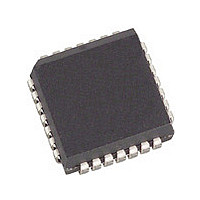
Mounting
Surface Mount
Pin Count
28
Lead Free Status / RoHS Status
Compliant
Available stocks
Company
Part Number
Manufacturer
Quantity
Price
Company:

Part Number:
COM20020I-DZD
Manufacturer:
Standard
Quantity:
17 665
Company:
Part Number:
COM20020I-DZD
Manufacturer:
SMSC
Quantity:
269
Company:
Part Number:
COM20020I-DZD
Manufacturer:
Microchip Technology
Quantity:
10 000
Company:
Part Number:
COM20020I-DZD-TR
Manufacturer:
Microchip Technology
Quantity:
10 000


Appendix A
Revision 12-05-06
This appendix describes the function of the NOSYNC and EF bits.
NOSYNC Bit
The NOSYNC bit controls whether or not the RAM initialization sequence requires the line to be idle by
enabling or disabling the SYNC command during initialization. It is defined as follows:
NOSYNC: Enable/Disable SYNC command during initialization. NOSYNC=0, Enable (Default): the line
has to be idle for the RAM initialization sequence to be written, NOSYNC=1, Disable: the line does not
have to be idle for the RAM initialization sequence to be written.
The following discussion describes the function of this bit:
During initialization, after the CPU writes the Node ID, the COM20020ID will write "D1"h data to Address
000h and Node-ID to Address 001h of its internal RAM within 6uS. These values are read as part of the
diagnostic test. If the D1 and Node-ID initialization sequence cannot be read, the initialization routine will
report it as a device diagnostic failure. These writes are controlled by a micro-program which sometimes
waits if the line is active; SYNC is the micro-program command that causes the wait. When the micro-
program waits, the initial RAM write does not occur, which causes the diagnostic error. Thus in this case,
if the line is not idle, the initialization sequence may not be written, which will be reported as a device
diagnostic failure.
However, the initialization sequence and diagnostics of the COM20020ID should be independent of the
network status. This is accomplished through some additional logic to decode the program counter,
enabled by the NOSYNC bit. When it finds that the micro-program is in the initialization routine, it disables
the SYNC command. In this case, the initialization will not be held up by the line status.
Thus, by setting the NOSYNC bit, the line does not have to be idle for the RAM initialization sequence to
be written.
EF Bit
The EF bit controls several modifications to internal operation timing and logic. It is defined as follows:
EF: Enable/Disable the new internal operation timing and logic refinements. EF=0: (Default) Disable the
new internal operation timing (the timing is the same as in the COM20020 Rev. B); EF=1: Enable the new
internal operation timing.
The EF bit controls the following timing/logic refinements in the COM20020ID:
While the interrupt is active (nINTR pin=0), the interrupt is disabled by writing the Clear Tx/Rx interrupt and
Clear Flag command and by reading the Next-ID register. This minimum disable time is changed by the
Data Rate. For example, it is 200 nS at 2.5 Mbps and 100 nS at 5 Mbps. The 100 nS width will be too
short to for the Interrupt to be seen.
Setting the EF bit will change the minimum disable time to always be more than 200 nS even if the Data
Rate is 5 Mbps . This is done by changing the clock which is supplied to the Interrupt Disable logic. The
frequency of this clock is always less than 20MHz even if the data rate is 5 Mbps.
The Pre-Scalar is used to change the data rate. The output clock is selected by CKP3-1 bits in the Set-Up
register. The CKP3-1 bits are changed by writing the Set-Up register from outside the CPU. It's not
a)
b)
Extend Interrupt Disable Time
Synchronize the Pre-Scalar Output
DATASHEET
Page 68
5Mbps ARCNET (ANSI 878.1) Controller with 2K x 8 On-Chip RAM
SMSC COM20020I Rev D
Datasheet
Related parts for COM20020I-DZD
Image
Part Number
Description
Manufacturer
Datasheet
Request
R


Part Number:
Description:
Manufacturer:
Standard Microsystems (SMSC)
Datasheet:

Part Number:
Description:
Manufacturer:
Standard Microsystems (SMSC)
Datasheet:
Part Number:
Description:
Manufacturer:
Standard Microsystems (SMSC)
Datasheet:
Part Number:
Description:
Manufacturer:
Standard Microsystems (SMSC)
Datasheet:
Part Number:
Description:
Manufacturer:
Standard Microsystems (SMSC)
Datasheet:
Part Number:
Description:
USB CHIP
Manufacturer:
Standard Microsystems (SMSC)
Datasheet:
Part Number:
Description:
Manufacturer:
Standard Microsystems (SMSC)
Datasheet:
Part Number:
Description:
ULTRA FAST USB 2.0 MULTI-SLOT FLASH MEDI
Manufacturer:
Standard Microsystems (SMSC)
Datasheet:
Part Number:
Description:
Manufacturer:
Standard Microsystems (SMSC)
Datasheet:

Part Number:
Description:
Manufacturer:
Standard Microsystems (SMSC)
Datasheet:
Part Number:
Description:
Manufacturer:
Standard Microsystems (SMSC)
Datasheet:
Part Number:
Description:
Manufacturer:
Standard Microsystems (SMSC)
Datasheet:
Part Number:
Description:
Manufacturer:
Standard Microsystems (SMSC)
Datasheet:
Part Number:
Description:
Manufacturer:
Standard Microsystems (SMSC)
Datasheet: