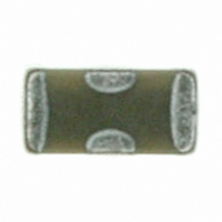
MCF182CN102M04AK Rohm Semiconductor, MCF182CN102M04AK Datasheet - Page 3

MCF182CN102M04AK
Manufacturer Part Number
MCF182CN102M04AK
Description
FILTER EMI 3-TERM 25V 4A 0603
Manufacturer
Rohm Semiconductor
Series
MCF18r
Datasheet
1.MCF182CN102M04AK.pdf
(7 pages)
Specifications of MCF182CN102M04AK
Capacitance
1000pF
Voltage
25V
Current
4A
Operating Temperature
-55°C ~ 125°C
Package / Case
0603 (1608 Metric)
Lead Free Status / RoHS Status
Lead free / RoHS Compliant
Dc Resistance (dcr)
-
Other names
511-1617-2
Available stocks
Company
Part Number
Manufacturer
Quantity
Price
Part Number:
MCF182CN102M04AK
Manufacturer:
ROHM/罗姆
Quantity:
20 000
○
MCF18
No.
10
c
www.rohm.com
7
8
9
2010 ROHM Co., Ltd. All rights reserved.
Temperature
characteristic
Solderability
Resistance
to solderin
heat
End termination
adherence
Without
voltage
application
Items
Dielectric
loss
tangent
Insulation
resistance
Appearance
Change
rate from
initial value
Change
rate from
initial value
+/−15%
(−55°C to +125°C)
More than 75% of each end
termination shall be covered with
new solder.
Without mechanical damage.
Within +/−7.5%
Within specified initial value.
Within specified initial value.
Without peeling or sign of
peeling shall be allowed
on the end terminations.
Performance
If required measurements shall be made at
a given temperature.
The solder specified in SnAg3.0Cu0.5
shall be used. And the flux containing 25%
rosin and ethanol solution shall be used.
The specimens shall be immersed into the
solder at 235+/−5°C for 2+/−0.5s
So that both end terminations are
completely under solder.
The solder specified in SnAg3.0Cu0.5
shall be used.
The specimens shall be immersed into the
solder at 260+/−5 °C for 5+/−0.5s so that
both end terminations are completely
under the solder.
Pre-heating at 150+/−10 °C for 1 to 2min
Initial measurements prior to test shall be
performed after the thermal
Pre-conditioning specified in Remarks (1).
Final measurements shall be made after the
specimens have been left at room
temperature as per Table3.
A 5N weight for 10+/−1s shall be applied
to the soldered specimens as shown by the
arrow mark in the below sketch.
3/6
Test Method
48+/−4 h
Filter
Table3
Time
Applied pressure
Substrate
2010.05 - Rev.F
Data Sheet


