MCP1790-5002E/EB Microchip Technology, MCP1790-5002E/EB Datasheet - Page 15
MCP1790-5002E/EB
Manufacturer Part Number
MCP1790-5002E/EB
Description
High Voltage, LDO, 70 MA 3 DDPAK TUBE
Manufacturer
Microchip Technology
Datasheet
1.MCP1791T-3302EDC.pdf
(34 pages)
Specifications of MCP1790-5002E/EB
Regulator Topology
Positive Fixed
Voltage - Output
5V
Voltage - Input
6 ~ 30 V
Voltage - Dropout (typical)
0.7V @ 70mA
Number Of Regulators
1
Current - Output
70mA (Min)
Operating Temperature
-40°C ~ 125°C
Mounting Type
Surface Mount
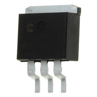
Package / Case
TO-263-3, D²Pak (3 leads + Tab), TO-263AA
Number Of Outputs
1
Polarity
Positive
Input Voltage Max
30 V
Output Voltage
5 V
Output Type
Fixed
Dropout Voltage (max)
1.3 V at 70 mA
Output Current
70 mA
Line Regulation
+/- 0.0002 % / V
Load Regulation
+/- 0.2 %
Voltage Regulation Accuracy
2.5 %
Maximum Operating Temperature
+ 125 C
Mounting Style
SMD/SMT
Minimum Operating Temperature
- 40 C
Lead Free Status / RoHS Status
Lead free / RoHS Compliant
Current - Limit (min)
-
Lead Free Status / Rohs Status
Lead free / RoHS Compliant
Available stocks
Company
Part Number
Manufacturer
Quantity
Price
Company:

Part Number:
MCP1790-5002E/EB
Manufacturer:
MICROCHIP
Quantity:
50 210


4.5
The MCP1791 has a Shutdown (SHDN) input signal
that enables or disables the regulator output voltage.
When the SHDN input signal is greater than 2.40V, the
regulator output voltage is enabled. Note that the
regulator output may still be disabled by the undervolt-
age lockout incorporated within the V
The value of the SHDN signal to put the regulator into
Shutdown mode is
by an internal resistor. If the SHDN pin is left floating,
the internal pull-down resistor will put the regulator into
shutdown mode.
When the SHDN input signal is pulled to a logic-low, the
PWRGD output signal will also go low and the regulator
will enter a low quiescent current state where the typi-
cal quiescent current is 10 µA. There is a short time
delay (approximately 400 ns) when the SHDN input
signal transitions from high to low to prevent signal
noise from disabling the regulator. The SHDN pin will
ignore low-going pulses that are up to 400 ns in pulse
width. If the SHDN input is pulled low for more than
400 ns, the regulator will enter Shutdown mode. This
small bit of filtering helps to reject any system noise
spikes on the SHDN input signal.
On the rising edge of the SHDN input, the shutdown
circuitry will have a 100 µs delay before allowing the
regulator output to turn on. This delay helps to reject
any false turn-on signals or noise on the SHDN input
signal. After the 100 µs delay, the regulator will start
charging the output capacitor as the regulator output
voltage rises from 0V to its final regulated value. The
charging current will be limited by the short circuit
current value of the device. If the SHDN input signal is
pulled low during the 100 µs delay period, the timer will
be reset and the delay time will start over again on the
next rising edge of the SHDN input. The total time from
the SHDN input going high (turn-on) to the regulator
output being in regulation shall typically be 200 µs
(100 µs + 100 µs) for a C
FIGURE 4-2:
Diagram.
© 2008 Microchip Technology Inc.
V
SHDN
OUT
100 µs
Shutdown (SHDN)
TOR
100 µs
≤
0.8V. The SHDN pin is pulled low
C
LOAD
Shutdown Input Timing
LOAD
= 1.0 µF
C
LOAD
= 1.0 µF.
C
HARGING
IN
400 ns (typ)
circuitry.
T
IME
4.6
The MCP1790/MCP1791 incorporates a Low Voltage
Shutdown circuit that turns off the output of the regula-
tor whenever the input voltage, V
specified turn off voltage, V
(V
stable regulation, the output voltage (V
the input down to approximately +4.00V. The regulator
will turn off the output at this point.
The output will turn on when V
value specified in the data sheet. This feature is
independent of the Shutdown input signal (SHDN) that
is provided for external regulator control. If the SHDN
input signal is active (LOW), then the output of the
regulator shall be disabled regardless of input voltage.
TABLE 4-1:
4.7
The MCP1790/MCP1791 requires a minimum output
capacitance of 1 µF tantalum or electrolytic capaci-
tance. The minimum value for ceramic capacitors is
4.7 µF. The regulator is stable for all three types of
capacitors from 4.7 µF to 1000 µF (see
The MCP1790/MCP1791 regulator may be used with a
1 µF ceramic output capacitor if a 0.300Ω resistor is
placed in series with the capacitor. The low ESR and
corresponding pole of the ceramic capacitor causes the
instability below 4.7 µF.
The Equivalent Series Resistance (ESR) of the output
capacitor must be no greater than 3 ohms. The output
capacitor should be located as close to the regulator
output as is practical. Ceramic materials X7R and X5R
have
recommended because of their size, cost, and
environmental robustness qualities.
B
) drops below the differential needed to provide
MCP1790/MCP1791
< V
< V
> V
> V
V
low
Low Voltage Shutdown
Output Capacitor
IN
OFF
OFF
ON
ON
temperature
SHUTDOWN LOGIC
SHDN
H
H
L
L
OFF
coefficients
. When the input voltage
IN
rises above the V
DS22075A-page 15
IN
, is below the
REG
V
Figure
) shall track
OFF
OFF
OFF
ON
OUT
and
4-3).
are
ON
Related parts for MCP1790-5002E/EB
Image
Part Number
Description
Manufacturer
Datasheet
Request
R

Part Number:
Description:
High Voltage, LDO, 50 mA, -40C to +125C, 8-SOIC 150mil, TUBE
Manufacturer:
Microchip Technology
Datasheet:

Part Number:
Description:
IC LDO REG 70MA 5.0V SOT-223-3
Manufacturer:
Microchip Technology
Datasheet:

Part Number:
Description:
IC LDO REG 70MA 3.3V 3DDPAK
Manufacturer:
Microchip Technology
Datasheet:
Part Number:
Description:
IC LDO REG 70MA 3.0V SOT-223-3
Manufacturer:
Microchip Technology
Datasheet:
Part Number:
Description:
IC LDO REG 70MA 3.3V SOT-223-3
Manufacturer:
Microchip Technology
Datasheet:
Part Number:
Description:
IC LDO REG 70MA 3.0V 3DDPAK
Manufacturer:
Microchip Technology
Datasheet:

Part Number:
Description:
70 Ma, High Voltage Regulator
Manufacturer:
Microchip Technology Inc.
Datasheet:
Part Number:
Description:
Manufacturer:
Microchip Technology Inc.
Datasheet:
Part Number:
Description:
Manufacturer:
Microchip Technology Inc.
Datasheet:
Part Number:
Description:
Manufacturer:
Microchip Technology Inc.
Datasheet:
Part Number:
Description:
Manufacturer:
Microchip Technology Inc.
Datasheet:
Part Number:
Description:
Manufacturer:
Microchip Technology Inc.
Datasheet: