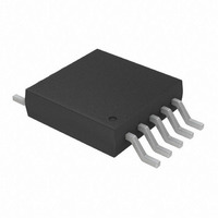
MCP73837-FJI/UN Microchip Technology, MCP73837-FJI/UN Datasheet - Page 5

MCP73837-FJI/UN
Manufacturer Part Number
MCP73837-FJI/UN
Description
1A USB/DC Input Auto-swich Li-Ion Charger PG Output 10 MSOP 3x3mm TUBE
Manufacturer
Microchip Technology
Datasheet
1.MCP73838T-FJIMF.pdf
(30 pages)
Specifications of MCP73837-FJI/UN
Function
Charge Management
Battery Type
Lithium-Ion (Li-Ion), Lithium-Polymer (Li-Pol)
Voltage - Supply
4.5 V ~ 6 V
Operating Temperature
-40°C ~ 85°C
Mounting Type
Surface Mount
Package / Case
10-TFSOP (0.118", 3.00mm Width)
Product
Charge Management
Output Voltage
4.2 V, 4.35 V, 4.4 V, 4.5 V
Output Current
1200 mA
Operating Supply Voltage
3.75 V to 6 V
Maximum Operating Temperature
+ 85 C
Minimum Operating Temperature
- 40 C
Mounting Style
SMD/SMT
Lead Free Status / RoHS Status
Lead free / RoHS Compliant
Lead Free Status / RoHS Status
Lead free / RoHS Compliant
DC CHARACTERISTICS (Continued)
© 2007 Microchip Technology Inc.
Electrical Specifications: Unless otherwise indicated, all limits apply for V
T
USB-Port Fast Charge Current
Maximum Output Current Limit
Precondition Current Regulation (Trickle Charge Constant-Current Mode)
Precondition Current Ratio
Precondition Current Threshold Ratio
Precondition Hysteresis
Charge Termination
Charge Termination Current Ratio
Automatic Recharge
Recharge Voltage Threshold Ratio
Pass Transistor ON-Resistance
ON-Resistance
Battery Discharge Current
Output Reverse Leakage Current
Status Indicators - STAT1, STAT2, PG (MCP73837)
Sink Current
Low Output Voltage
Input Leakage Current
PROG1 Input (PROG1)
Charge Impedance Range
Shutdown Impedance
PROG2 Inputs (PROG2)
Input High Voltage Level
Input Low Voltage Level
Shutdown Voltage Level
Input Leakage Current
Note 1:
A
= -40°C to +85°C. Typical values are at +25°C, V
2:
3:
4:
The supply voltage (V
when input power source is from USB-Port.
The value is guaranteed by design and not production tested.
The current is based on the ratio of selected current regulation (I
The maximum charge impedance has to be less than shutdown impedance for normal operation.
Parameters
DD
) = V
AC
V
V
I
I
I
PREG
TERM
DISCHARGE
PTH
RTH
R
R
R
when input power source is from Ac-Adapter and the supply voltage (V
V
Sym
I
I
I
V
V
PHYS
DSON
SINK
PROG
PROG
REG
MAX
V
I
V
I
LK
LK
/ V
/ V
SD
OL
IH
IL
/ I
/ I
REG
REG
REG
REG
DD
= [V
0.8V
0.2V
REG
3.75
Min
400
7.5
5.6
7.5
80
—
15
30
64
69
—
15
92
95
—
—
—
—
—
—
—
70
—
—
1
DD
DD
(typical) + 1.0V]
1200
66.5
71.5
94.0
0.55
0.03
Typ
450
100
120
350
7.5
0.1
0.3
90
10
20
40
10
20
97
16
—
—
—
—
—
-6
5
7
DD
REG
= [V
).
REG
0.2V
0.8V
Max
12.5
6.25
12.5
100
500
200
9.4
-15
25
50
69
74
25
96
99
35
15
—
—
—
—
—
2
2
1
1
(typical) + 0.3V] to 6V,
DD
DD
Units
mA
mA
mA
mV
mΩ
mA
µA
µA
µA
µA
kΩ
kΩ
µA
%
%
%
%
%
%
%
%
%
%
%
%
%
%
%
V
MCP73837/8
PROG2 = Low
PROG2 = High
T
PROG1 < 833Ω
Note 3
T
V
V
PROG1 = 1 kΩ to 10 kΩ
T
Note 3
V
T
V
Standby (PROG1 or PROG2
Floating)
Shutdown (V
100 mV or V
Charge Complete
I
High Impedance, V
Note 4
Minimum Impedance for
Shutdown
V
SINK
A
A
A
A
BAT
BAT
BAT
DD
PROG2
=-5°C to +55°C
=-5°C to +55°C
=-5°C to +55°C
=-5°C to +55°C
= 4.5V, T
Low to High
High to Low
High to Low
= 4 mA
= V
Conditions
DD
DD
DS22071A-page 5
DD
J
DD
= 105°C
< V
< V
) = V
STOP
DD
BAT
on pin
USB
-
)


