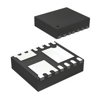
MIC2550AYML25 TR Micrel Inc, MIC2550AYML25 TR Datasheet - Page 9

MIC2550AYML25 TR
Manufacturer Part Number
MIC2550AYML25 TR
Description
USB Transceiver -
Manufacturer
Micrel Inc
Type
USB Transceiverr
Datasheet
1.MIC2550AYML_TR.pdf
(11 pages)
Specifications of MIC2550AYML25 TR
Number Of Drivers/receivers
1/1
Protocol
USB 2.0
Voltage - Supply
4 V ~ 5.25 V
Mounting Type
Surface Mount
Package / Case
14-MLF®, QFN
Number Of Transceivers
1
Esd Protection
YeskV
Operating Supply Voltage (typ)
Not RequiredV
Operating Temperature Classification
Industrial
Operating Supply Voltage (max)
Not RequiredV
Operating Supply Voltage (min)
Not RequiredV
Pin Count
16
Mounting
Surface Mount
Operating Temperature (max)
85C
Operating Temperature (min)
-40C
Lead Free Status / RoHS Status
Lead free / RoHS Compliant
Other names
MIC2550AYML25TR
MIC2550AYML25TR
MIC2550AYML25TR
PCB Layout Recommendations
Although the USB standard and applications are not based in
an impedance controlled environment, a properly designed
PCB layout is recommended for optimal transceiver perfor-
mance. The suggested PCB layout hints are as follows:
March 2005
MIC2550A
• Match signal line traces (VP/VM, D+, D–) to
• For every signal line trace width (w), separate
• Maintain the same number of vias on each
• Control signal line impedances to ±10%.
• Keep R
40ps, approximately
PCB material propagation is about 150ps/inch,
so to minimize skew try to keep VP/VM, D+/D–
traces as short as possible.
the signal lines by 1.5–2 widths. Place all other
traces at >2w from all signal line traces.
differential trace, keeping traces approximately
at same separation distance along the line.
equal distance between R
D+ and D–.
S
as close to the IC as possible, with
1
/
3
inch if possible. FR-4
S
and the IC for both
9
M9999-031805
Micrel, Inc.


