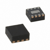
MIC44F18YML TR Micrel Inc, MIC44F18YML TR Datasheet

MIC44F18YML TR
Specifications of MIC44F18YML TR
MIC44F18YML TR
MIC44F18YMLTR
MIC44F18YMLTR
Related parts for MIC44F18YML TR
MIC44F18YML TR Summary of contents
Page 1
... MOSFET Driver with 6.2V UVLO Externally Set MLF and MicroLeadFrame are registered trademarks of Amkor Technologies, Inc. Micrel Inc. • 2180 Fortune Drive • San Jose, CA 95131 • USA • tel +1 (408) 944-0800 • fax + 1 (408) 474-1000 • February 2011 6A, 13V High Speed MOSFET Drivers Features • ...
Page 2
Micrel, Inc. Ordering Information Part Number Marking Configuration D12 MIC44F18YML Non-Inverting MIC44F18YMME Non-Inverting D13 MIC44F19YML Inverting Output high when disabled MIC44F19YMME Inverting Output high when disabled D14 MIC44F20YML Inverting Output low when disabled MIC44F20YMME Inverting Output low when disabled Note: ...
Page 3
Micrel, Inc. Logic Table EN/UVLO February 2011 MIC44F18 MIC44F19 OUTPUT OUTPUT LOW HI LOW HI LOW HI HI LOW 3 MIC44F18/19/20 MIC44F20 OUTPUT LOW LOW HI LOW M9999-020111 ...
Page 4
Absolute Maximum Ratings Supply Voltage (V ). ………………………………….. 14V dd UVLO/Enable Voltage (V )…………………....... 14V UVLO/EN Input Voltage (V ) …………… Output Voltage (V ) ……………………………........ 14V OUT Junction Temperature (T )…………………... ..........150°C J Ambient Storage Temperature ...
Page 5
Electrical Characteristics (Continued) 4.5V< V < 13.2V; C =1000pf 25°C, bold values indicate –40°C< Symbol Parameter Output V High Output Voltage OH V Low Output Voltage OL Output Resistance, Output High R O Output ...
Page 6
Typical Characteristics February 2011 6 M9999-020111 ...
Page 7
Typical Characteristics cont. February 2011 7 M9999-020111 ...
Page 8
Timing Diagram Functional Diagram February 2011 Figure 1. MIC44F18/19/20 Functional Block Diagram 8 M9999-020111 ...
Page 9
Functional Description The MIC44F18/19/20 family of drivers are high speed, high current drivers that are designed to drive P-channel and N-channel MOSFETs. The drivers come in both inverting and non-inverting versions. The block diagram of the MIC44Fxx driver is shown ...
Page 10
Output Driver Section A block diagram of the low-side driver is shown in Figure 3. Low driver impedances allow the external MOSFET to be turned on and off quickly. The rail-to-rail drive capability of the output ensures a low R ...
Page 11
Micrel, Inc. Application Information Power Dissipation Considerations Power dissipation in the driver can be separated into two areas: • Output driver stage dissipation • Quiescent current dissipation used to supply the internal logic and control functions. Output Driver Stage Power ...
Page 12
Micrel, Inc. The power dissipated inside the MIC4100/4101 is equal to the ratio of R & the external resistive losses in ON OFF R and R . Letting G_FET ON OFF the MIC44F18 due ...
Page 13
Micrel, Inc. Figure 6C. Maximum Driver Power Dissipation Propagation Delay and Delay Matching and Other Timing Considerations Fast propagation delay between the input and output drive waveform is desirable. It improves overcurrent protection by decreasing the response time between the ...
Page 14
Micrel, Inc. Figure 8 shows the critical current paths when the driver outputs go low and turn off the external MOSFETs. Short, low impedance connections are important during turn-off for the same reasons given in the turn-on explanation. Current from ...
Page 15
Micrel, Inc. The following circuit guidelines should be adhered to for optimum circuit performance: 1. The V bypass capacitor must be placed close to the CC VDD and ground pins critical that the etch length between the decoupling ...
Page 16
Package Information February 2011 8-Pin ePad MSOP (MME) 8-Pin 2mm x 2mm MLF (ML) 16 M9999-020111 ...
Page 17
MICREL, INC. 2180 FORTUNE DRIVE SAN JOSE, CA 95131 USA TEL +1 (408) 944-0800 FAX +1 (408) 474-1000 WEB Micrel makes no representations or warranties with respect to the accuracy or completeness of the information furnished in this data sheet. ...


