TMP37GT9Z Analog Devices Inc, TMP37GT9Z Datasheet - Page 15
TMP37GT9Z
Manufacturer Part Number
TMP37GT9Z
Description
3V TEMPERATURE SENSOR
Manufacturer
Analog Devices Inc
Datasheet
1.TMP35GT9Z.pdf
(20 pages)
Specifications of TMP37GT9Z
Sensing Temperature
5°C ~ 100°C
Output Type
Voltage
Voltage - Supply
2.7 V ~ 5.5 V
Accuracy
±1°C
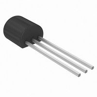
Package / Case
TO-226-3, TO-92-3 (TO-226AA)
Lead Free Status / RoHS Status
Lead free / RoHS Compliant


USING TMP3x SENSORS IN REMOTE LOCATIONS
In many industrial environments, sensors are required to
operate in the presence of high ambient noise. These noise
sources take many forms, for example, SCR transients, relays,
radio transmitters, arc welders, and ac motors. They can also
be used at considerable distances from the signal conditioning
circuitry. These high noise environments are typically in the
form of electric fields, so the voltage output of the temperature
sensor can be susceptible to contamination from these noise
sources.
Figure 32 illustrates a way to convert the output voltage of a
TMP3x sensor into a current to be transmitted down a long
twisted pair shielded cable to a ground referenced receiver. The
temperature sensors are not capable of high output current
operation; thus, a standard PNP transistor is used to boost the
output current drive of the circuit. As shown in the table in
Figure 32, the values of R2 and R3 were chosen to produce an
arbitrary full-scale output current of 2 mA. Lower values for the
full-scale current are not recommended. The minimum-scale
output current produced by the circuit could be contaminated
by ambient magnetic fields operating in the near vicinity of the
circuit/cable pair. Because the circuit uses an external transistor,
the minimum recommended operating voltage for this circuit is
5 V. To minimize the effects of EMI (or RFI), both the circuit
and the temperature sensor supply pins are bypassed with good
quality ceramic capacitors.
Figure 32. Remote, 2-Wire Boosted Output Current Temperature Sensor
0.1µF
0.01µF
SENSOR R2
TMP35
TMP36
TMP37
1k
634
887
4.7kΩ
TMP3x
R1
R3
1k
634
887
+V
GND
S
2N2907
V
R2
OUT
TWISTED PAIR
BELDEN TYPE 9502
OR EQUIVALENT
5V
R3
V
OUT
Rev. F | Page 15 of 20
TEMPERATURE TO 4–20 mA LOOP TRANSMITTER
In many process control applications, 2-wire transmitters are
used to convey analog signals through noisy ambient environ-
ments. These current transmitters use a zero-scale signal current
of 4 mA, which can be used to power the signal conditioning
circuitry of the transmitter. The full-scale output signal in these
transmitters is 20 mA.
Figure 33 illustrates a circuit that transmits temperature inform-
ation in this fashion. Using a TMP3x as the temperature sensor,
the output current is linearly proportional to the temperature of
the medium. The entire circuit operates from the 3 V output of
the REF193. The REF193 requires no external trimming because
of its tight initial output voltage tolerance and the low supply
current of the TMP3x, the OP193, and the REF193. The entire
circuit consumes less than 3 mA from a total budget of 4 mA.
The OP193 regulates the output current to satisfy the current
summation at the noninverting node of the OP193. A generalized
expression for the KCL equation at Pin 3 of the OP193 is given by
For each temperature sensor, Table 5 provides the values for the
components P1, P2, and R1 to R4.
Table 5. Circuit Element Values for Loop Transmitter
Sensor
TMP35
TMP36
TMP37
The 4 mA offset trim is provided by P2, and P1 provides the
full-scale gain trim of the circuit at 20 mA. These two trims do
not interact because the noninverting input of the OP193 is
held at a virtual ground. The zero-scale and full-scale output
currents of the circuit are adjusted according to the operating
temperature range of each temperature sensor. The Schottky
diode, D1, is required in this circuit to prevent loop supply
power-on transients from pulling the noninverting input of the
OP193 more than 300 mV below its inverting input. Without
this diode, such transients can cause phase reversal of the
operational amplifier and possible latch-up of the transmitter.
The loop supply voltage compliance of the circuit is limited by
the maximum applied input voltage to the REF193; it is from
9 V to 18 V.
I
OUT
R1
97.6 kΩ
97.6 kΩ
97.6 kΩ
=
⎛
⎜
⎝
R7
1
⎞
⎟
⎠
×
P1
5 kΩ
5 kΩ
5 kΩ
⎛
⎜ ⎜
⎝
TMP3x
R1
R2
1.58 MΩ
931 kΩ
10.5 kΩ
×
TMP35/TMP36/TMP37
R3
+
V
REF
P2
100 kΩ
50 kΩ
500 Ω
R2
×
R3
⎞
⎟ ⎟
⎠
R3
140 kΩ
97.6 kΩ
84.5 kΩ
R4
56.2 kΩ
47 kΩ
8.45 kΩ
Related parts for TMP37GT9Z
Image
Part Number
Description
Manufacturer
Datasheet
Request
R

Part Number:
Description:
±1.7g Dual-Axis IMEMS Accelerometer Evaluation Board
Manufacturer:
Analog Devices Inc
Datasheet:

Part Number:
Description:
Inertial Sensor Evaluation System
Manufacturer:
Analog Devices Inc
Datasheet:
Part Number:
Description:
Manufacturer:
Analog Devices Inc
Datasheet:
Part Number:
Description:
Manufacturer:
Analog Devices Inc
Datasheet:
Part Number:
Description:
Manufacturer:
Analog Devices Inc
Datasheet:
Part Number:
Description:
Manufacturer:
Analog Devices Inc
Datasheet:
Part Number:
Description:
Manufacturer:
Analog Devices Inc
Datasheet:
Part Number:
Description:
Manufacturer:
Analog Devices Inc
Datasheet:
Part Number:
Description:
Manufacturer:
Analog Devices Inc
Datasheet:
Part Number:
Description:
Manufacturer:
Analog Devices Inc
Datasheet:
Part Number:
Description:
Manufacturer:
Analog Devices Inc
Datasheet:
Part Number:
Description:
Manufacturer:
Analog Devices Inc
Datasheet:
Part Number:
Description:
Manufacturer:
Analog Devices Inc
Datasheet: