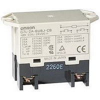
G7L-1A-BUB-J-CB-AC100/120 Omron, G7L-1A-BUB-J-CB-AC100/120 Datasheet

G7L-1A-BUB-J-CB-AC100/120
Specifications of G7L-1A-BUB-J-CB-AC100/120
Related parts for G7L-1A-BUB-J-CB-AC100/120
G7L-1A-BUB-J-CB-AC100/120 Summary of contents
Page 1
... SPST-NO (with test button) DPST-NO PCB mounting SPST-NO DPST-NO Note: 1. When ordering, add the rated coil voltage to the model number. Example: G7L-1A-T 12 VAC (~) 5. Rated Coil Voltage AC: 12, 24, 50, 100 to 120, 200 to 240 DC: 6, 12, 24, 48, 100 Upper bracket With test button Quick-connect ...
Page 2
... SPST-NO G7L-1A-B G7L-1A-BJ DPST-NO G7L-2A-B G7L-2A-BJ Applicable Relay G7L-1A-T/G7L-1A-TJ/G7L-1A-B/G7L-1A-BJ G7L-2A-T/G7L-2A-TJ/G7L-2A-B/G7L-2A-BJ G7L-1A-T/G7L-1A-TJ/G7L-2A-T/G7L-2A-TJ G7L-1A-B/G7L-1A-BJ/G7L-1A-BUB/G7L-1A-BUBJ G7L-2A-B/G7L-2A-BJ/G7L-2A-BUB/G7L-2A-BUBJ Application Examples • Compressors for air conditioners and heater switching controllers. • Switching controllers for power tools or motors. • Power controllers for water heaters. • Power controllers for dryers. ...
Page 3
... Electrical:100,000 operations min. (at 1,800 operations/hr under rated load) Operating: – (with no icing) Operating 85% Quick-connect terminal models:approx PCB terminal models:approx. 100 g Screw terminal models: approx. 120 g G7L-1A-P/G7L-2A-P Inductive load Resistive load Inductive load (cos = 0.4) (cos = 1) (cos = 0. 220 VAC (~) 4,400 VAC (~) G7L Power Relay 177 ...
Page 4
... SPST-NO G7L-2A-P DPST-NO TÜV: File No. R9051158 (VDE 0435, IEC 255, IEC 950, EN60950) Model Contact Form G7L-1A-B@ SPST-NO G7L-2A-B@ DPST-NO G7L-1A-T@ SPST-NO G7L-2A-T@ DPST-NO G7L-1A-P SPST-NO G7L-2A-P DPST-NO G7L 178 Power Relay Coil ratings Contact ratings 12 to 240 VAC 30 A, 277 VAC (RES) ...
Page 5
... VAC resistive load 220 VAC inductive load (cos = 0.4) Switching current (A) Endurance 220 VAC resistive load 220 VAC inductive load (cos = 0.4) Switching current (A) Endurance 220 VAC resistive load 220 VAC inductive load (cos = 0.4) Switching current (A) Power Relay G7L 179 ...
Page 6
... Quick-connect Terminals with DIN Track Mounting Adapter Note: 1. The DIN Track Mounting Adapter and DIN tracks are sold separately. 2. The DIN Track Mounting Adapter can be track-mounted or screw-mounted. G7L-1A-T PFP-@N 55.5 max. G7L 180 Power Relay Terminal Arrangement/ Internal Connections (Top View) ...
Page 7
... Internal Connections G7L (Top View) 0 51.5 max max. 5 66.5 max. P7LF-D G7L 0 51.5 max. 2 Test button 63 max. 5 66.5 max. P7LF-D G7L 0 51.5 max Test button 63 max. 5 66.5 max. Terminal Arrangement/ P7LF-06 G7L Internal Connections (Top View) 51.5 max. 0 61.5 max max. ...
Page 8
... Two, M3.5 screws PFP-@N for coil with Test Button 55.5 max. Four, M4 screws for contact ■ Quick-connect Terminals with Upper Bracket G7L-1A-TUB G7L-2A-TUB G7L-1A-TUBJ with Test Button G7L 182 Power Relay P7LF-06 Terminal Arrangement/ G7L Internal Connections (Top View) 51.5 max Test button 61 ...
Page 9
... Two, M3.5 screws for coil G7L-2A-B Two, M3.5 screws for coil G7L-1A-BJ with Test Button Two, M3.5 screws for coil G7L-2A-BJ with Test Button Two, M3.5 screws for coil Terminal Arrangement/ Mounting Holes Internal Connections (Top View) Two, 4.5-dia. hole or M4 tapped holes ...
Page 10
... G7L-2A-BJ with Test Button PFP-@N 55.5 max. ■ Screw Terminals with Upper Bracket G7L-1A-BUB Two, M3.5 screws for coil G7L 184 Power Relay P7LF-D Terminal Arrangement/ G7L Internal Connections (Top View) 51.5 max. 0 65.5 max max. P7LF-D G7L 51.5 max 65.5 max. ...
Page 11
... Test Button Two, M3.5 screws for coil G7L-2A-BUBJ with Test Button Two, M3.5 screws for coil ■ PCB Terminals with PCB Mounting G7L-1A-P G7L-2A-P Four, M4 screws for contact Terminal Arrangement/ Mounting Holes Internal Connections Two, 4.5-dia. hole (Top View tapped holes ...
Page 12
... E-bracket P7LF-D Adapter P7LF-06 Two, M3.5 screws Front-connecting for coil Socket Four, M4 screws for contact P7LF-C Cover 34.5 max. ■ Internal Coil Circuit DC Operating Coil G7L 186 Power Relay Two, 4.5-dia. 40 holes 0.1 35.2 max. 55.5 max ...
Page 13
... If a transistor drives the G7L check the leakage current, and connect a bleeder resistor if necessary. The AC coil is provided with a built-in full-wave rectifier triac, such as an SSR, drives the G7L, the G7L may not release. Be sure to perform a trial operation with the G7L and the triac before applying them to actual use. ...


