E2E-X3D2-N Omron, E2E-X3D2-N Datasheet - Page 13
E2E-X3D2-N
Manufacturer Part Number
E2E-X3D2-N
Description
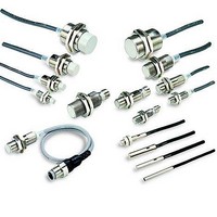
Proximity Sensors PROX M12 3MM NC
Manufacturer
Omron
Series
E2Er
Specifications of E2E-X3D2-N
Proximity Sensor Type
Inductive
Proximity Sensor Sensing Distance
3mm
Proximity Sensor Sensing Distance Range
2 to 7mm
Proximity Sensor Switching Mode
NC
Mounting
Panel
Operating Temp Range
-25C to 70C
Operating Temperature Classification
Commercial
Operating Supply Voltage (min)
10V
Operating Supply Voltage (typ)
12/15/18/24V
Operating Supply Voltage (max)
30V
Pin Count
4
Output Type
NPN/PNP
Maximum Operating Temperature
+ 70 C
Supply Voltage
30 V
Output Voltage
3 V
Operating Supply Voltage
12 V to 24 V
Mounting Style
Panel
Sensing Distance
3 mm
Minimum Operating Temperature
- 25 C
Maximum Output Current
100 mA
Features
High visibility indicator
Sensor Type
Inductive
Sensing Object
Metallic
Response Frequency
1kHz
Material - Body
Nickel-Plated Brass
Shielding
Shielded
Voltage - Supply
10 V ~ 30 V
Terminal Type
2-Wire
Package / Case
Cylinder, Threaded - M12
Lead Free Status / RoHS Status
Compliant
Available stocks
Company
Part Number
Manufacturer
Quantity
Price
Company:

Part Number:
E2E-X3D2-N
Manufacturer:
ZETEX
Quantity:
22 043


Ratings and Specifications
E2E-X@D@ DC 2-Wire Models
*1. Use the E2E within the range in which the setting indicator (green LED) is ON (except D2 Models).
*2. The response frequency is an average value.
*3. The residual voltage of each M1J-T Model is 5 V. When connecting to a device, make sure that the device can withstand the residual voltage. (Refer to page 29 for
Item
Sensing distance
Set distance *1
Differential travel
Detectable object
Standard sensing
object
Response frequency
*2
Power supply voltage
(operating voltage
range)
Leakage current
Control
output
Indicators
Operation mode
(with sensing object
approaching)
Diagnostic output
delay
Protection circuits
Ambient
temperature range
Ambient
humidity range
Temperature
influence
Voltage influence
Insulation resistance
Dielectric strength
Vibration resistance
Shock resistance
Degree of protection
Connection method
Weight
(pack-
ed
state)
Materi-
als
Accessories
Measurement conditions are as follows: standard sensing object, a distance of twice the standard sensing object, and a set distance of half the sensing distance.
details.)
Pre-wired
Models
Pre-wired
Connector
Models
Connector
Models
Case
Sensing sur-
face
Clamping
nuts
Toothed
washer
Load
current
Residual
voltage
*3
Shielded
Model E2E-X2D@
Size
2 mm ±10%
0 to 1.6 mm
15% max. of sensing distance
Ferrous metal (The sensing distance decreases with non-ferrous metal. Refer to Engineering Data on pages 18 and 19.
Iron,
8 × 8 × 1 mm
1.5 kHz
12 to 24 VDC (10 to 30 VDC), ripple (p-p): 10% max.
0.8 mA max.
3 to 100 mA, Diagnostic output: 50 mA for -D1(5)S Models
3 V max. (Load current: 100 mA, Cable length: 2 m, M1J-T Models only: 5 V max.)
D1 Models: Operation indicator (red) and setting indicator (green)
D2 Models: Operation indicator (red)
D1 Models: NO
D2 Models: NC
0.3 to 1 s
Surge suppressor, Load short-circuit protection (for control and diagnostic output)
Operating: −25 to 70°C, Storage: −40 to 85°C (with no icing or condensation)
Operating/storage: 35% to 95% (with no condensation)
±15% max. of sensing distance
at 23°C in the temperature range
of −25 to 70°C
±1% max. of sensing distance at rated voltage in the rated voltage ±15% range
50 MΩ min. (at 500 VDC) between current-carrying parts and case
1000 VAC, 50/60 Hz for 1 minute between current carry parts and case
Destruction: 10 to 55 Hz, 1.5-mm double amplitude for 2 hours each in X, Y, and Z directions
Destruction: 500 m/s
10 times each in X, Y, and
Z directions
Pre-wired Models: IEC 60529 IP67, in-house standards: oil-resistant
Connector Models: IEC 60529 IP67
Pre-wired Models (Standard cable length: 2 m), Connector Models, or Pre-wired Connector Models (Standard cable length: 0.3 m)
Approx. 60 g
Approx. 15 g
Stainless steel (SUS303)
PBT
Nickel-plated brass
Zinc-plated iron
Instruction manual
Shielded
M8
---
E2E-X4MD@
4 mm ±10%
0 to 3.2 mm
Iron,
20 × 20 × 1 mm
1 kHz
Unshielded
Refer to the timing charts under I/O Circuit Diagrams on page 21 for details.
2
E2E-X3D@
3 mm ±10%
0 to 2.4 mm
10% max. of sensing distance
Iron,
12 × 12 × 1 mm
±10% max. of sensing distance at 23°C in the temperature range of −25 to 70°C
Destruction: 1,000 m/s
Approx. 70 g
Approx. 40 g
Approx. 25 g
Nickel-plated brass
Shielded
M12
E2E-X8MD@
8 mm ±10%
0 to 6.4 mm
Iron,
30 × 30 × 1 mm
0.8 kHz
Unshielded
2
10 times each in X, Y, and Z directions
E2E-X7D@
7 mm ±10%
0 to 5.6 mm
Iron,
18 × 18 × 1 mm
0.5 kHz
Approx. 130 g
Approx. 70 g
Approx. 40 g
Shielded
M18
E2E-X14MD@
14 mm ±10%
0 to 11.2 mm
Iron, 30 × 30 × 1 mm
0.4 kHz
Unshielded
E2E-X10D@
10 mm ±10%
0 to 8 mm
Approx. 110 g
Approx. 175 g
Approx. 90 g
Shielded
M30
E2E-X20MD@
20 mm ±10%
0 to 16 mm
Iron,
54 × 54 × 1 mm
0.1 kHz
Unshielded
E2E
13
Related parts for E2E-X3D2-N
Image
Part Number
Description
Manufacturer
Datasheet
Request
R

Part Number:
Description:
E2E-X1C1 W/ ROBOTIC CABLE
Manufacturer:
Omron
Datasheet:
Part Number:
Description:
Proximity Sensors E2E-X5ME1 W/5M CABLE
Manufacturer:
Omron
Datasheet:
Part Number:
Description:
Proximity Sensors Prox Plug In
Manufacturer:
Omron
Datasheet:
Part Number:
Description:
Proximity Sensors PROX E2E-C1C1 W/ 5 M ETER CABLE
Manufacturer:
Omron
Datasheet:
Part Number:
Description:
Proximity Sensors E2E-X1C1 W/ SPECIAL ATTRIBUTES
Manufacturer:
Omron
Datasheet:
Part Number:
Description:
Proximity Sensors PROX E2E-CR8C1 ROBOT CABLE 2M
Manufacturer:
Omron
Datasheet:
Part Number:
Description:
Proximity Sensors E2E-X1B1 W/ 2M ROBOT IC CABLE
Manufacturer:
Omron
Datasheet:
Part Number:
Description:
Proximity Sensors Proximity Sensor
Manufacturer:
Omron
Datasheet:
Part Number:
Description:
Proximity Sensors PROXIMITY SENSOR
Manufacturer:
Omron
Datasheet:
Part Number:
Description:
Proximity Sensors Prox M18 7Mm Nc
Manufacturer:
Omron
Datasheet:

Part Number:
Description:
PROXIMITY SENSOR
Manufacturer:
Omron
Datasheet:
