AML24FBE3CA01 Honeywell, AML24FBE3CA01 Datasheet - Page 5
AML24FBE3CA01
Manufacturer Part Number
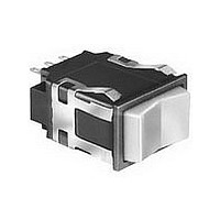
AML24FBE3CA01
Description
Rocker Switches & Paddle Switches DPDT 2POS 1LAMP 28V RECT. ROCKER SW
Manufacturer
Honeywell
Specifications of AML24FBE3CA01
Pole Throw Configuration
DPDT
Switch Configuration
N.O./N.C.
Actuator Style
Rocker
Illumination Type
Incandescent Lamp
Contact Material
Silver
Mounting Style
Through Hole
Terminal Type
PC Pins/Push-On
Contact Form
DPDT
Contact Rating
2 Amps to 3 Amps
Actuator
Rocker
Contact Plating
Silver
Lead Free Status / RoHS Status
Compliant


Manual Switches
Electronic Control Paddle
LED DISPLAY
Covers with LED ‘‘window’’ ordered separately.
AML25 ORDER GUIDE
Example: AML25FBB2AA01RX
Rectangular paddle switch; illuminated
with one red LED, this device has a black
paddle and bezel, and .110
nals; with one circuit ON and one circuit
OFF in each extreme operator position
(maintained).
NOTE: For further information on re-
placement LED’s, call the 800 number.
Honeywell Sensing and Control 1-800-537-6945 USA
AML25 F
Rectangular
Rectangular
AML25 G
AML25 F
Housing
2 LED’s
1 LED
Type
Bezel Color
Black/Black
Operator/
B
B
.020 termi-
* See LED application information for devices without current-limiting resistor, page 46.
Voltage
LED
10 V
15 V
24 V
5 V
V*
B
C
B
D
E
F
FEATURES
Identical to AML23, except furnished
with one or two rectangular high
efficiency LED’s which give flush
display area and wide angle
indication.
Available with or without diode
protection for LED’s.
LED circuit independent of switch
circuit.
Diode Protection
Terminal Type/
(Solder or Q-C)
(Printed Ckt.,
.110
.025
or Push-On
.110
protection
w/Diode
1-815-235-6847 International 1-800-737-3360 Canada
2
2
3
8
.020
.025
.020
as shown in
LED version
Insert code
Circuitry
available
only with
Circuitry
Covers
ordered
separately
circuitry
Codes
letters
Chart
AA
AA
BA
CA
DA
Insert code
Operating
Operating
numbers
Electrical Data
Paddle Covers
Lamps and LEDs
Accessories
Mounting Dimensions
1 The ‘‘MICRO SWITCH’’ identification is
Action
Code
Chart
from
01
5 thru 24 VDC devices have internal
resistor to maintain current at nominal
20 mA.
UL recognized, CSA certified.
shown on this side of the switch housings.
LED Color
(LED A)
No LED
Yellow
Green
*AML25 Series: 1 pole and
2-pole only.
Red
R
G
R
Y
X
AML25 Series
17
*
pages 47/50
page 11
page 36
page 46
page 45
LED Color
(LED B)
No LED
Yellow
Green
Red
X
R
G
Y
X
*
Related parts for AML24FBE3CA01
Image
Part Number
Description
Manufacturer
Datasheet
Request
R

Part Number:
Description:
SWITCH ROCKER AML RECT SPDT 3POS
Manufacturer:
Honeywell Sensing and Control
Datasheet:

Part Number:
Description:
SWITCH ROCKER AML RECT SPDT 2POS
Manufacturer:
Honeywell Sensing and Control
Datasheet:

Part Number:
Description:
SWITCH ROCKER AML RECT SPDT 2POS
Manufacturer:
Honeywell Sensing and Control
Datasheet:

Part Number:
Description:
AML24 SERIES ROCKER SWITCH, DPDT, 3 POSITION, SILVER CONTACTS, 0.110 IN X 0.020 IN (SOLDER OR QUICK-CONNECT), NON-LIGHTED, RECTANGLE, SNAP-IN PANEL
Manufacturer:
Honeywell Sensing and Control


Part Number:
Description:
HONEYWELL ZEPHYR DIGITAL AIRFLOW SENSORS: HAF SERIES-HIGH ACCURACY
Manufacturer:
HONEYWELL [Honeywell Solid State Electronics Center]
Datasheet:
Part Number:
Description:
MOUNTING BARRIER FOR HONEYWELL SERIES 2 OPERATOR INTERFACE PUSHBUTTON SWITCHES
Manufacturer:
Honeywell Sensing and Control
Part Number:
Description:
SEALED OI-SE SWITCH . PER TERRY @ HONEYWELL THERE IS A CHG OF $5.00 EACH FOR P
Manufacturer:
Honeywell Sensing and Control
Part Number:
Description:
LIMIT SWITCH-OT/HONEYWELL KOREA RELAYS (YKC)
Manufacturer:
Honeywell Sensing and Control
Part Number:
Description:
Honeywell Zephyr Digital Airflow Sensors Series-high Accuracy
Manufacturer:
Honeywell International's Solid State Electronics Center (SSEC)
Datasheet:

Part Number:
Description:
DIODE IR EMITTING GAAS SIDE LOOK
Manufacturer:
Honeywell Sensing and Control
Datasheet:

Part Number:
Description:
DIODE IR EMITTING ALGAAS TO-46
Manufacturer:
Honeywell Sensing and Control
Datasheet:

Part Number:
Description:
SENSOR AMP 150PSIS .5-4.5VDC OUT
Manufacturer:
Honeywell Sensing and Control
Datasheet: