High Current, Power Inductors
HCM0703 Series
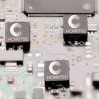
Description
• Halogen Free
• 125°C maximum total temperature operation
• 7.4 x 7.0 x 3.0mm maximum surface mount package
• Powder iron core material
• Magnetically shielded, low EMI
• High current carrying capacity, Low core losses
• Inductance range from 0.15μH to 10.0μH
• Current range from 3.2 to 52 Amps
• Frequency range up to 5MHz
• RoHS compliant
1 Open Circuit Inductance (OCL) Test Parameters: 100kHz, 0.25V rms , 0.0Adc, @ +25°C.
2 Full Load Inductance (FLL) Test Parameters: 100kHz, 0.25V rms , I sat @ +25°C.
3 I rms : DC current for an approximate temperature rise of 40°C without core loss. Derating is
4 I sat : Peak current for approximately 20% rolloff at +25°C.
0910
Part
Number
HCM0703-R15-R
HCM0703-R22-R
HCM0703-R47-R
HCM0703-R68-R
HCM0703-R82-R
HCM0703-1R0-R
HCM0703-1R5-R
HCM0703-2R2-R
HCM0703-3R3-R
HCM0703-4R7-R
HCM0703-6R8-R
HCM0703-8R2-R
HCM0703-100-R
necessary for AC currents. PCB layout, trace thickness and width, air-flow and proximity of other
heat generating components will affect the temperature rise. It is recommended that the
temperature of the part not exceed 125°C under worst case operating conditions verified in the
end application.
BU-SB10995
SMD Device
6
OCL
±20%
0.15
0.22
0.47
0.68
0.82
1.00
1.50
2.20
3.30
4.70
6.80
8.20
10.0
1
(μH)
FLL min,
(μH)
0.09
0.13
0.28
0.41
0.49
0.60
0.90
1.32
1.98
2.82
4.08
4.92
6.00
2
Product Specifications
(Amps)
I rms
26.0
23.0
17.5
15.5
13.0
11.0
9.00
8.00
6.00
5.50
4.50
4.00
3.20
3
5 K-factor: Used to determine B p-p for core loss (see graph). B p-p = K * L * ΔI. B p-p (Gauss),
6 Part Number Definition: HCM0703-xxx-R
I sat
Applications
•
•
•
•
•
•
•
•
•
Environmental Data
• Storage temperature range: -55°C to +125 °C
• Operating temperature range: -55°C to +125°C
• Solder reflow temperature: J-STD-020D compliant
Packaging
• Supplied in tape and reel packaging, 1,500 parts per
K: (K-factor from table), L: (inductance in μH), ΔI (peak-to-peak ripple current in amps).
• HCM0703 = Product code and size
• xxx= Inductance value in μH, R = decimal point,
• “-R” suffix = RoHS compliant
If no R is present then 3
(Amps)
Voltage Regulator Module (VRM)
Multi-phase regulators
Point-of-load modules
Desktop and server VRMs and EVRDs
Base station equipment
Notebook regulators
Battery power systems
Graphics cards
Data networking and storage systems
(ambient plus self-temperature rise)
13” diameter reel
4
Page 1 of 4
52.0
40.0
26.0
25.0
24.0
22.0
18.0
14.0
13.5
10.0
8.00
7.50
7.00
@ 25°C
DCR (mΩ) @ 20°C DCR (mΩ) @ 20°C
rd
digit equals number of zeros.
(Typical)
1.90
2.50
4.00
5.00
6.70
9.00
14.0
18.0
28.0
37.0
54.0
64.0
70.5
Data Sheet: 4085
HF
FREE
HALOGEN
(Maximum)
2.50
2.80
4.20
5.50
8.00
10.0
15.0
20.0
30.0
40.0
60.0
68.0
77.6
Pb
K-factor
1610.3
615.4
430.2
367.4
286.2
259.7
175.7
163.6
158.2
118.1
106.8
95.3
81.2
5