BZE6-7RNT Honeywell, BZE6-7RNT Datasheet - Page 48
BZE6-7RNT
Manufacturer Part Number
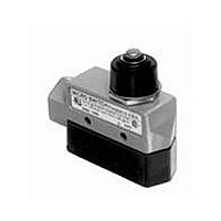
BZE6-7RNT
Description
Basic / Snap Action / Limit Switches Top Plunger Actuator 14 NPT conduit
Manufacturer
Honeywell
Type
Basicr
Specifications of BZE6-7RNT
Pole Throw Configuration
SPDT
Switch Function Configuration
N.O./N.C.
Current Rating (max)
15A
Terminal Type
Screw
Contact Form
SPDT - 1 NC / 1 NO
Contact Rating
15 Amps
Actuator
Plunger
Operating Force
7.78 N to 15.01 N
Termination Style
Screw
Ingress Protection
IP66 / NEMA 1, 3, 4
Actuator Type
Plunger
Brand/series
E6 Series
Current, Rating
0.5 A
Ip Rating
IP54
Material, Contact
Zinc Die-Cast (Housing)
Mounting Type
Side Mount
Number Of Poles
1
Number Of Positions
2
Standards
UL Recognized, CSA Certified, NEMA Approved
Temperature, Operating
-32 to +71 °C
Termination
Screw
Lead Free Status / RoHS Status
Compliant


Basic Switches
Miniature
PIN PLUNGERS
For application help: call 1-800-537-6945.
Dim. Dwg. Fig. 1
Dim. Dwg. Fig. 2
SIMULATED
Dim. Dwg. Fig. 3
ROLLER
ORDER GUIDE by ascending electrical capability
*For actuators, contact MICRO SWITCH Sales Office.
ORDER GUIDE
V3-343-D8
V3-2451-D8
V3-2401-D8
V3-70101-D8
V3-1101-D8
V3-2101-D8
V3-101-D8
V3-1-D8
V3-3001-D8
V3-2800-D9
V3-2900-D9
V3-1001
(MS25253-1)
V3-1002
(MS25253-3)
V3-1003
(MS25253-2)
V3-129*
V3-245*
V3L-1123-D8
V3L-2105-D8
V3L-121-D8
V3L-5-D8
V3L-3014-D8
Catalog
Catalog
Listing
Listing
Recommended For
General use.
Low force.
High force. Most
applications.
Highest force. Up to
15.1 amps load
handling with
reduced life.
High force. Up to
15.1 amps load
handling.
General use. Gold
alloy crosspoint
contacts.
Lowest force.
Lower force.
Most 5 amp
applications.
General use.
Low force.
Higher force. Most
applications.
Highest force. Up to
15.1 amps load
handling with reduced
life.
High force. Up to 15.1
amps load handling.
Up to 20 amps load
handling
Up to 25 amps load
handling
MIL-S-8805 application
requirements (SPDT)
MIL-S-8805 application
requirements (SPNC)
MIL-S-8805 application
requirements (SPNO)
Operating in
temperature to
Operating in
temperature to
Recommended For
302 F (150 C)
400 F (204 C)
Electrical Length of
Data And Lever ‘‘A’’
15.1 Amps
15.1 Amps
UL Code
Page 20
10 Amps
10 Amps
11 Amps
Characteristics: O.F. – Operating Force; R.F. – Release Force; P .T. –
Pretravel; O.T. – Overtravel; D.T. – Differential Travel; O.P . – Operating
Position.
15.1 Amps
15,1 Amps
Electrical
Data And
UL Code
Page 20
10 Amps
10 Amps
11 Amps
20 Amps
25 Amps
10 Amps
10 Amps
10 Amps
11 Amps
10 Amps
TT
U
U
3 Amps
5 Amps
5 Amps
V
T
1 Amp
VV
UU
UU
UU
YY
AA
BB
ZZ
TT
W
X
V
U
U
T
T
Obsolete
inches
1.285
1.285
1.285
1.285
1.285
0,63 - 1,22
1,22 - 2,20
newtons newtons
0,72 max.
0,50 max.
1,47 max.
mm
32,6
32,6
32,6
32,6
32,6
1,67-3,89
1,67-3,89
1,67-3,89
1,67-3,89
2,78-6,95
ounces
2.3 - 4.4
4.4 - 7.9
8 max.
8 max.
8 max.
10-25
2,22
0,15
0,24
2,22
2,22
6-14
6-14
6-14
6-14
2,22
O.F.
.53
2.6
1.8
5.3
.9
8
Honeywell
newtons newtons
ounces
max.
O.F.
0,39
0,33
1,11
2,22
0,94
ounces
1.4
1.2
3.4
4
8
min.
0,56
0,56
0,10
0,05
0,56
1,11
0,15
0,20
0,31
1,11
1,11
1,11
0,56
1,67
R.F.
.35
.18
.53
0.7
1.1
—
—
2
2
2
4
4
4
4
2
6
MICRO SWITCH Sensing and Control
ounces
min.
R.F.
0,05
0,02
0,14
0,28
0,07
.18
.07
.25
.5
1
inches
max.
mm
.047
.047
.047
.047
.047
.047
.047
1,21
.047
.047
.047
.047
.047
.047
.047
.047
.047
P.T.
1,2
1,2
1,2
1,2
1,2
1,2
1,2
1,2
1,2
1,2
1,2
1,2
1,2
1,2
1,2
inches
max.
.100
.100
.125
.125
.100
mm
2,54
2,54
3,18
3,18
2,54
P.T.
inches
min.
O.T.
mm
1,02
.040
1,27
.050
1,27
.050
1,02
.040
1,27
.050
1,27
.050
1,02
.040
.040
1,27
.050
1,27
.050
1,27
.050
1,02
.040
1,02
.040
1,02
.040
1,02
.040
1,02
.040
1,0
inches
min.
.080
.080
.062
.062
.075
O.T.
mm
2,03
2,03
1,57
1,57
1,90
0,051-0,25
0,051-0,25
0,051-0,25
0,051-0,25
0,051-0,25
.010 max.
0,15-0,41
.006-.016
.002-.010
.002-.010
0,15-0,41
.006-.016
.002-.010
.002-.010
0,15-0,41
.006-.016
.006-.016
.002-.010
.010 max
0,15-0,41
.006-.016
0,15-0,41
.006-.016
0,15-0,41
.006-.016
0,15-0,41
.006-.016
0,15-0,41
.006-.016
0,15-0,4
inches
mm
0,25
0,25
D.T.
**Tolerances
inches
V3 Series
max.
.030
.030
.032
.032
.030
D.T.
mm
0,76
0,76
0,81
0,81
0,76
* 1.5 mm
inches
O.P.**
inches
mm
14,7
.578
14,7
.578
14,7
.578
14,7
.578
14,7
.578
14,7
.578
14,7
.578
14,7
.578
14,7
.578
14,7
.578
14,7
.578
14,7
.578
14,7
.578
14,7
.578
14,7
.578
14,7
.578
O.P.*
.730
.730
.730
.730
.730
mm
18,5
18,5
18,5
18,5
18,5
.060 in.
0.38
0.15
33
Related parts for BZE6-7RNT
Image
Part Number
Description
Manufacturer
Datasheet
Request
R

Part Number:
Description:
Basic / Snap Action / Limit Switches Limit Switch E6 ENCLOSURES(BZE6)
Manufacturer:
Honeywell

Part Number:
Description:
Basic / Snap Action / Limit Switches E6 ENCLOSURES(BZE6)
Manufacturer:
Honeywell

Part Number:
Description:
Basic / Snap Action / Limit Switches Limit Switch E6 ENCLOSURES(BZE6)
Manufacturer:
Honeywell

Part Number:
Description:
Basic / Snap Action / Limit Switches Limit Switch E6 ENCLOSURES(BZE6)
Manufacturer:
Honeywell

Part Number:
Description:
Basic / Snap Action / Limit Switches Limit Switch E6 ENCLOSURES(BZE6)
Manufacturer:
Honeywell
Part Number:
Description:
Basic / Snap Action / Limit Switches E6 ENCLOSURES(BZE6)
Manufacturer:
Honeywell

Part Number:
Description:
Basic / Snap Action / Limit Switches Limit Switch E6 ENCLOSURES(BZE6)
Manufacturer:
Honeywell

Part Number:
Description:
Basic / Snap Action / Limit Switches Limit Switch E6 ENCLOSURES(BZE6)
Manufacturer:
Honeywell

Part Number:
Description:
Basic / Snap Action / Limit Switches Limit Switch E6 ENCLOSURES(BZE6)
Manufacturer:
Honeywell

Part Number:
Description:
SWITCH TOP PLUNGER SPDT 15A
Manufacturer:
Honeywell Sensing and Control
Datasheet:
Part Number:
Description:
SWTCH TOP PLNGR SNAP SPDT ENCLSD
Manufacturer:
Honeywell Sensing and Control
Datasheet:

Part Number:
Description:
SWITCH TOP PLNGR SNAP SPDT
Manufacturer:
Honeywell Sensing and Control
Datasheet:
Part Number:
Description:
SWTCH TOP PLNGR SNAP SPDT ENCLSD
Manufacturer:
Honeywell Sensing and Control
Datasheet:
Part Number:
Description:
SWITCH TOP ROLLER ARM SPDT 15A
Manufacturer:
Honeywell Sensing and Control
Datasheet:
Part Number:
Description:
SWITCH TOP ROLLR PLNGR SNAP SPDT
Manufacturer:
Honeywell Sensing and Control
Datasheet: