G5CA1AEDC5 Omron, G5CA1AEDC5 Datasheet - Page 4
G5CA1AEDC5
Manufacturer Part Number
G5CA1AEDC5
Description
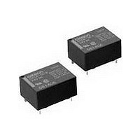
Electromechanical Relay SPST-NO 15A 5VDC 125Ohm Through Hole
Manufacturer
Omron
Type
Power Relayr
Datasheet
1.G5CA-1A_DC12.pdf
(8 pages)
Specifications of G5CA1AEDC5
Contact Arrangement
SPST-NO
Dc Coil Voltage
5 V
Coil Current
40 mA
Mounting
Through Hole
Relay Construction
Non-Latching
Coil Voltage Dc
5V
Contact Form
1 Form A
Voltage Rating (vdc)
125V
Voltage Rating (vac)
250V
Dropout Volt (min)
0.5VDCV
Coil Resistance
125Ohm
Pick-up Voltage (max)
3.75VDC
Maximum Power Rating
300W/2.5KVA
Operate Time
10ms
Contact Current Rating
15A
Contact Material
Silver
Coil Suppression Diode
No
Push To Test Button
No
Led Indicator
No
Seal
Flux
Product Height (mm)
11mm
Product Depth (mm)
16mm
Product Length (mm)
22mm
Operating Temp Range
-25C to 70C
Pin Count
4
Mounting Style
Through Hole
Termination Style
PC Pin
Lead Free Status / Rohs Status
Compliant


Engineering Data
Dimensions
Note: All units are in millimeters unless otherwise indicated.
188
G5CA-1A(-E)
G5CA-1A4(-H)
Maximum Switching Capacity
Operating Temperature vs.
Must-operate/Must-release Voltage
Note: The "maximum voltage" is the maximum
100
80
60
40
20
0.7
0.5
0.3
0.1
50
30
15
10
0
−40
7
5
3
1
1
AC resistive load
G5CA-1A-E
Sample: G5CA-1A DC
No. of samples: 5
voltage that can be applied to the relay coil,
but, not continously.
DC inductive load
G5CA-1A
G5CA-1A-E
(L/R=7 ms)
DC resistive load
G5CA-1A
G5CA-1A-E
−20
3
5 7 10
PCB Relay
0
AC resistive load
G5CA-1A
AC inductive
load
G5CA-1A
(cos φ=0.4)
11 max.
(10.9)*
3.5
30 50 100
20
1.6
Must-operate voltage
Must-release voltage
Ambient temperature (˚C)
Switching voltage (V)
G5CA
40
10.16
AC inductive
load
G5CA-1A-E
(cos φ=0.4)
22 max.
(21.9)*
300 500 1,000
60
max.
min.
max.
min.
7.62
X
X
80
Electrical Service Life
0.6
500
300
100
70
50
30
10
7
5
3
1
0
0.3
Malfunction Shock
1,000 min.
1,000 min.
2
* Average value
X
Z'
30-VDC resistive load
16 max.
(15.9)*
4
12.7
6
1,000 min.
250-VAC resistive load
8
200
400
600
800
0.4
Y'
Y
110-VAC resistive load
1,000 min.
800
600
400
200
10
Mounting Holes (PCB)
(BOTTOM VIEW)
Tolerance: ±0.1 mm
Switching current (A)
2.54
Two, 1 dia.
elliptic holes
12
Y
Y'
Shock direction
X
Unit: m/s
14
1,000 min.
1,000 min.
2.54
10.16
16
Z
X'
X'
2
17.78
Z
Z'
Ambient Temperature vs.
Maximum Coil Voltage
200
180
160
150
140
130
120
100
80
60
2
0
No. of samples: 10
Measured value: The value at which
Standard:
Two, 1 dia. hole
20
12.7
30
Continuous max.
permissile voltage (15 A)
Note: Orientation marks are
Terminal Arrangement/
Internal Connections
40
(BOTTOM VIEW)
indicated as follows:
Continuous max.
permissile voltage (10 A)
(No coil polarity)
malfunction occurs
in the contact when
the contact is
subjected to shock
three times each in
six directions for
three axes.
200 m/s
50
1
4
Ambient temperature (˚C)
60
2
3
70
2
80
90
Related parts for G5CA1AEDC5
Image
Part Number
Description
Manufacturer
Datasheet
Request
R

Part Number:
Description:
Power PCB Relay
Manufacturer:
Omron
Datasheet:
Part Number:
Description:
Power PCB Relay
Manufacturer:
Omron
Datasheet:
Part Number:
Description:
Power PCB Relay
Manufacturer:
Omron
Datasheet:
Part Number:
Description:
Power PCB Relay
Manufacturer:
Omron
Datasheet:

Part Number:
Description:
Power PCB Relay
Manufacturer:
Omron
Datasheet:
Part Number:
Description:
Power PCB Relay
Manufacturer:
Omron
Datasheet:

Part Number:
Description:
Power PCB Relay
Manufacturer:
Omron
Datasheet: