2222 153 61108 Vishay, 2222 153 61108 Datasheet - Page 3
2222 153 61108
Manufacturer Part Number
2222 153 61108
Description
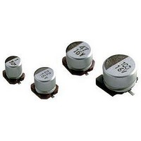
CAPACITOR ALUM ELECT 1UF, 50V, SMD
Manufacturer
Vishay
Series
153 CLVr
Datasheet
1.MAL215376339E3.pdf
(9 pages)
Specifications of 2222 153 61108
Capacitor Dielectric Type
Aluminium Electrolytic
Capacitance Tolerance
± 20%
Esr
12ohm
Life Time @ Temperature
2000 Hours @ 105°C
Capacitance
1µF
Voltage Rating
50VDC
Lead Free Status / RoHS Status
Lead free / RoHS Compliant


153 CRV
Vishay BCcomponents
Table 2
MOUNTING
The capacitors are designed for automatic placement on to
printed-circuit boards.
Optimum dimensions of soldering pads depend amongst
others on soldering method, mounting accuracy, print layout
and/or adjacent components.
For recommended soldering pad dimensions, refer to Fig.3
and Table 3.
SOLDERING
Soldering conditions are defined by the curve, temperature
versus time, where the temperature is that measured on the
soldering pad and on top of the case during processing.
For maximum conditions refer to Fig.4.
Maximum 2 runs with pause of minimum 30 min between.
Any temperature versus time curve which does not exceed
the specified maximum curves may be applied.
Table 3
www.vishay.com
52
DIMENSIONS in millimeters AND MASS
RECOMMENDED SOLDERING PAD DIMENSIONS in millimeters
4.0 x 4.0 x 5.3
5.0 x 5.0 x 5.3
6.3 x 6.3 x 5.3
8.0 x 8.0 x 6.5
8.0 x 8.0 x 10
10 x 10 x 10
10 x 10 x 12
10 x 10 x 14
CASE SIZE
L x W x H
NOMINAL
CASE CODE
0405
0505
0605
0807
0810
1010
1012
1014
CODE
CASE
0405
0505
0605
0807
0810
1010
1012
1014
L
For technical questions, contact: aluminumcaps1@vishay.com
10.6
10.6
10.6
max.
4.5
5.5
6.8
8.6
8.6
W
SMD (Chip) Long Life Vertical
10.6
10.6
10.6
max.
4.5
5.5
6.8
8.6
8.6
2.6
3.0
3.5
4.0
3.5
4.0
4.3
4.3
a
Aluminum Capacitors
H
10.5
10.5
12.3
14.3
max.
5.5
5.5
5.5
6.8
Ø D
10.0
10.0
10.0
4.0
5.0
6.3
8.0
8.0
AS A GENERAL PRINCIPLE, TEMPERATURE AND DURATION
SHALL BE THE MINIMUM NECESSARY REQUIRED TO
ENSURE GOOD SOLDERING CONNECTIONS. HOWEVER, THE
SPECIFIED
EXCEEDED.
B
max.
0.8
0.8
0.8
0.8
1.1
1.1
1.2
1.2
1.6
1.6
1.6
1.6
2.5
2.5
2.5
2.5
b
1.0
1.4
2.0
2.3
3.1
4.7
4.5
4.5
S
MAXIMUM
Fig.3
≈ 0.13
≈ 0.20
≈ 0.30
≈ 0.50
≈ 1.00
≈ 1.30
≈ 1.40
≈ 1.50
MASS
(g)
Recommended soldering
pad dimensions
CURVES
0.4 ± 0.2
Fig.2 Dimensional outline
Document Number: 28388
SHOULD
W
W B
0.3
max.
Revision: 15-Oct-08
1.0
1.4
1.9
2.1
3.0
4.0
4.0
4.0
c
NEVER
S
D
L
BE
Related parts for 2222 153 61108
Image
Part Number
Description
Manufacturer
Datasheet
Request
R

Part Number:
Description:
CAPACITOR ALUM ELECT 22UF 35V SMD
Manufacturer:
Vishay
Datasheet:
Part Number:
Description:
CAPACITOR ALUM ELECT 100UF 50V SMD
Manufacturer:
Vishay
Datasheet:
Part Number:
Description:
CAPACITOR ALUM ELECT 10UF 50V SMD
Manufacturer:
Vishay
Datasheet:
Part Number:
Description:
CAPACITOR ALUM ELECT 4.7UF 50V SMD
Manufacturer:
Vishay
Datasheet:
Part Number:
Description:
CAPACITOR ALUM ELECT 47UF 50V SMD
Manufacturer:
Vishay
Datasheet:
Part Number:
Description:
CAPACITOR ALUM ELECT 100UF, 6.3V, SMD
Manufacturer:
Vishay
Datasheet:
Part Number:
Description:
CAPACITOR ALUM ELECT 220UF 10V SMD
Manufacturer:
Vishay
Datasheet:
Part Number:
Description:
CAPACITOR ALUM ELECT 10UF 16V SMD
Manufacturer:
Vishay
Datasheet:
Part Number:
Description:
CAPACITOR ALUM ELECT 47UF 16V SMD
Manufacturer:
Vishay
Datasheet:
Part Number:
Description:
CAPACITOR ALUM ELECT 100UF 25V SMD
Manufacturer:
Vishay
Datasheet:

Part Number:
Description:
357-036-542-201 CARDEDGE 36POS DL .156 BLK LOPRO
Manufacturer:
Vishay
Datasheet:
Part Number:
Description:
357-036-542-201 CARDEDGE 36POS DL .156 BLK LOPRO
Manufacturer:
Vishay
Datasheet:
Part Number:
Description:
357-036-542-201 CARDEDGE 36POS DL .156 BLK LOPRO
Manufacturer:
Vishay
Datasheet:
Part Number:
Description:
357-036-542-201 CARDEDGE 36POS DL .156 BLK LOPRO
Manufacturer:
Vishay
Datasheet:
Part Number:
Description:
357-036-542-201 CARDEDGE 36POS DL .156 BLK LOPRO
Manufacturer:
Vishay
Datasheet: