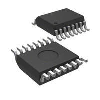
MIC74BQS Micrel Inc, MIC74BQS Datasheet

MIC74BQS
Specifications of MIC74BQS
Related parts for MIC74BQS
MIC74BQS Summary of contents
Page 1
... Outputs can directly drive LEDs (10mA I • devices per bus Applications • General purpose I/O expansion via serial bus • Personal computer system management • Distributed sensing and control • Microcontroller I/O expansion • Fan Control Ordering Information Standard MIC74BQS 3.0V MIC74 R9 VDD P0 /ALERT P1 ALERT DATA ...
Page 2
Micrel, Inc. Pin Configuration Pin Description Pin Number Pin Name 1 – – – – GND P4 – – 12 (/SHDN, /FS0 – FS2) 13 /ALERT 14 CLK 15 DATA ...
Page 3
Micrel, Inc. Absolute Maximum Ratings Supply Voltage (V )...................................................+4.6V DD Input Voltage [all pins except and GND] (V )........................ GND – 0. Junction Temperature (T ) ....................................... +150°C J Lead Temperature (soldering, 10 sec.).................... +260°C ...
Page 4
Micrel, Inc. Symbol Parameter AC Characteristics t Fan Startup Interval START t Minimum Pulse-Width PULSE t Interrupt Delay /INT Delay from Status Read or ARA t /IR Response to /ALERT ≥ Hold Time, Note 7 HD:STA t Setup ...
Page 5
Micrel, Inc. Register Descriptions Device Configuration Register DEV_CFG D[7] D[6] D[5] D[4] D[3] Always write as zero Power-On Default Value: 0000 0000 Interrupts disabled Not in Fan Mode Command_byte addess: 0000 0000 Type: 8-bits, read/write Bit Name: IE Function: Global ...
Page 6
Micrel, Inc. Interrupt Mask Register INT_MASK D[7] D[6] D[5] D[4] D[3] IM7 IM6 IM5 IM4 IM3 Power-On Default Value:0000 0000 Command_byte addess: 0000 0100 Type: 8-bits, read/write Bit Name: IMn Function: Interrupt enable bit for Pn when Pn is configured ...
Page 7
Micrel, Inc. Functional Diagram INTn IMn STATUSn STATUS_READn DATAn (INPUT) OUT_CFGn DIRn DATAn (OUTPUT) Functional Description Pin Descriptions VDD Power supply input connection. See “Operating Ratings.” GND Ground or return connection for all MIC74 functions. CLK An CLK signal is ...
Page 8
Micrel, Inc. Pn, /SHDN, and /FS0–/FS2 P0 through P7 are general-purpose input/output bits. Each bit is independently programmable as an input or an output. If programmed as an output, each bit is further programmable as either a complementary push- pull ...
Page 9
Micrel, Inc. Register Name DEV_CONFIG Device Configuration DIR OUT_CFG Output Configuration STATUS Interrupt Status INT_MASK Interrupt Mask DATA General-Purpose I/O FAN_SPEED Fan Start-Up Any time the fan speed register contains zero (fan is off) and then a nonzero value is ...
Page 10
Micrel, Inc. Fan Supply shutdown Value written to FAN_SPEED (00 /FS2 /FS1 /FS0 /SHDN Figure 2. Typical MIC74 Fan-Mode Timing and System Behavior October 2006 Fan Output Rotation Voltage* Speed START h ...
Page 11
Micrel, Inc. Application Information Bit Transfer The data received on the DATA pin must be stable during the high period of the clock. DATA CLK Data Change Allowed Figure 3. Acceptable Bit Transfer Conditions Data can change state only when ...
Page 12
Micrel, Inc. P0* /ALERT Figure 7. Interrupt Handling Using the Alert Response Address R/W = WRITE Slave Address (host addresses an MIC74) P0* t /INT /ALERT * Assumes P0 interrupts ...
Page 13
Micrel, Inc. Initializing the MIC74 The MIC74’s internal registers are reset to their default state at power-on. The MIC74’s default state can be summarized as follows: • All I/O’s configured as inputs (DIR = 00h) • Output configuration set to ...
Page 14
Micrel, Inc. Polled Mode Input state changes on I/O’s configured as inputs will be reflected in the status register regardless of the state of the global interrupt enable bit (IE) and the individual interrupt mask bits in INT_MASK ...
Page 15
Micrel, Inc. The act of reading STATUS clears it in preparation for detecting future events. The status bits corresponding to I/O’s configured as outputs or corresponding to P[7:4] when in fan mode will not be set by state changes on ...
Page 16
Micrel, Inc. Regardless of which procedure is used important that only one software routine at a time attempts to make changes to the output data system where polling is the exclusive method for servicing inputs, this ...
Page 17
Micrel, Inc. the fan will be shutdown by the assertion of the /SHDN output if FAN_SPEED is zero. If FAN_SPEED is programmed with any nonzero value, the fan will be driven to its maximum speed for the duration of t ...
Page 18
Micrel, Inc. Package Information MICREL, INC. 2180 FORTUNE DRIVE SAN JOSE, CA 95131 USA TEL +1 (408) 944-0800 FAX +1 (408) 474-1000 WEB http:/www.micrel.com The information furnished by Micrel in this data sheet is believed to be accurate and reliable. ...


