E5CSV-R1KJ-W AC100-240 Omron, E5CSV-R1KJ-W AC100-240 Datasheet - Page 9
E5CSV-R1KJ-W AC100-240
Manufacturer Part Number
E5CSV-R1KJ-W AC100-240
Description
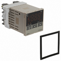
CONTROL TEMP DGTL RELAY OUT
Manufacturer
Omron
Series
E5CSVr
Type
Temperature Controller, Digitalr
Specifications of E5CSV-R1KJ-W AC100-240
Input Type
Thermocouple (J, K, L)
Controller Type
On/Off or Proportional (PID)
Temperature Range
Selectable, Varies By Input Type
Output Type
Relay
Supply Voltage
100 ~ 240VAC
Size
48mm W x 48mm H (1/16 DIN)
Display Type
4 Digit
Lead Free Status / RoHS Status
Lead free / RoHS Compliant
Features
-
Communications
-
Other names
E5CSV-R1KJ-W-AC100-240
E5CSV-R1KJ-W-AC100240
E5CSVR1KJWAC100240
Z2694
E5CSV-R1KJ-W-AC100240
E5CSVR1KJWAC100240
Z2694


4. Using the Control Mode Switches
(1) Using ON/OFF Control and PID Control
ON/OFF Control
The control mode is set to ON/OFF control as the default setting.
PID Control
Turn ON switch 1 to use PID control.
1. Set the control period.
ST (Self-tuning) Features
ST (self-tuning) is a function that finds PID constants by
using step response tuning (SRT) when Controller oper-
ation begins or when the set point is changed. Once the
PID constants have been calculated, ST is not executed
when the next control operation is started as long as the
set point remains unchanged. When the ST function is
in operation, be sure to turn ON the power supply of the
load connected to the control output simultaneously with
or before starting Controller operation.
Performing Control via Relay Output, External Relay, or Con-
ductor
Switch 2: OFF (control period: 20 s)
Quick Control Response Using an SSR
Switch 2: ON (control period: 2 s)
Control output
Control output
Control output
ON
ON
Switch 1 ON: PID control
1
1
ON
1
Switch 1 OFF: ON/OFF control
OFF
OFF
ON
2
ON
2
ON
1
2
2
3
3
OFF
ON
3
2 s
3
4
4
4
20 s
4
5
5
SP
5
5
6
6
6
6
Executing AT (Auto-tuning)
AT (auto-tuning) is executed by pressing the U Up and D Down Keys for at
least 2 s while the PV is displayed. The deviation indicators flash during auto-
tuning (AT) execution. AT will be cancelled by performing the same operation
that AT is executing during AT operation. Flashing stops when AT is completed.
Note: One of the deviation indicators (▲■▼) will flash.
To perform cooling control of freezers, etc., turn ON switch 3.
2. Set direct/reverse operation for the output.
AT execution
AT cancelled
Performing Heating Control for Heaters
Switch 3: OFF
Performing Cooling Control for Freezers
Switch 3: ON
Temperature Controllers
100%
100%
ON
ON
0%
0%
Control output
1
1
AT execution in progress
2
2
ON
1
3
3
2
OFF
ON
4
4
at least 2 s.
at least 2 s.
U D
U D
Press for
Press for
3
SP
SP
5
5
4
AT execution in progress
E5CSV
SP
6
6
5
Output level
Output level
6
9