SY100H641AJC Micrel Inc, SY100H641AJC Datasheet - Page 3
SY100H641AJC
Manufacturer Part Number
SY100H641AJC
Description
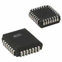
IC CLOCK DRIVER 1:9 28-PLCC
Manufacturer
Micrel Inc
Series
Precision Edge®r
Type
Fanout Buffer (Distribution)r
Datasheet
1.SY100H641AJC.pdf
(5 pages)
Specifications of SY100H641AJC
Number Of Circuits
1
Ratio - Input:output
1:9
Differential - Input:output
Yes/Yes
Input
PECL
Output
TTL
Frequency - Max
80MHz
Voltage - Supply
4.75 V ~ 5.25 V
Operating Temperature
0°C ~ 85°C
Mounting Type
Surface Mount
Package / Case
28-LCC (J-Lead)
Frequency-max
80MHz
Lead Free Status / RoHS Status
Contains lead / RoHS non-compliant
Available stocks
Company
Part Number
Manufacturer
Quantity
Price


V
NOTE:
1. V
V
NOTE:
1. V
V
NOTES:
1. Device-to-Device Skew considering HIGH-to-HIGH transitions at common
2. Within-Device Skew considering HIGH-to-HIGH transitions at common
SEMICONDUCTOR
Symbol
I
I
V
V
V
Symbol
I
I
V
V
V
Symbol
t
t
t
t
t
t
t
t
t
t
t
f
—
—
t
t
T
T
T
IH
IL
IH
IL
PLH
PHL
skpp
skew++
skew– –
PLH
PHL
PLH
PHL
r
f
MAX
S
H
10H ECL DC ELECTRICAL CHARACTERISTICS
100H ECL DC ELECTRICAL CHARACTERISTICS
AC ELECTRICAL CHARACTERISTICS
SYNERGY
IH
IL
BB
IH
IL
BB
power supply voltage.
power supply voltage.
= V
= V
= V
IH
IH
, V
, V
E
E
E
IL
IL
= 5.0V
= 5.0V
= 5.0V
and V
and V
Input HIGH Current
Input LOW Current
Input HIGH Voltage
Input LOW Voltage
Output Reference Voltage
Input HIGH Current
Input LOW Current
Input HIGH Voltage
Input LOW Voltage
Output Reference Voltage
Propagation Delay
D to Output
Part-to-Part Skew
Within-Device Skew
Within-Device Skew
Propagation Delay
LEN to Output
Propagation Delay
EN to Output
Output Rise/Fall Time
0.8V to 2.0V
Maximum Input Frequency
Pulse Width
Recovery Time
Set-up Time
Hold Time
BB
BB
are referenced to V
are referenced to V
5%
5%
5%
Parameter
Parameter
Parameter
(1)
(1)
(1)
(1)
(1,4)
E
E
(2,4)
(3,4)
and will vary 1:1 with the power supply. The levels shown are for V
and will vary 1:1 with the power supply. The levels shown are for V
(1)
(1)
(5,6)
3.830
3.050
3.620
3.835
3.190
3.620
Min.
Min.
0.5
0.5
—
—
T
T
A
A
= 0 C
= 0 C
1.25
5.0
4.9
5.0
1.5
Min.
4.120
3.525
3.740
80
—
—
—
—
—
Max.
4.160
3.520
3.730
225
Max.
T
225
—
0.5 (typ.)
0.5 (typ.)
—
A
= 0 C
Max.
5-358
6.0
0.5
0.3
0.3
6.9
7.0
1.7
1.6
—
—
—
3.870
3.050
3.650
3.835
3.190
3.620
Min.
Min.
0.5
0.5
3. Within-Device Skew considering LOW-to-LOW transitions at common
4. All skew parameters are guaranteed but not tested.
5. Frequency at which output levels will meet a 0.8V to 2.0V minimum swing.
6. The f
T
T
—
—
A
A
power supply voltage.
frequency. Actual operational maximum frequency may be greater.
= +25 C
= +25 C
Min.
1.25
T
5.0
4.9
4.9
1.5
—
—
—
—
—
80
A
0.5 (typ.)
0.5 (typ.)
= +25 C
MAX
4.190
3.520
3.750
4.120
3.525
3.740
Max.
Max.
175
175
—
—
value is specified as the minimum guaranteed maximum
Max.
6.0
0.5
0.3
0.3
6.9
6.9
1.7
1.6
—
—
—
3.940
3.050
3.690
Min.
3.835
3.190
3.620
0.5
Min.
T
—
0.5
T
—
A
1.25
5.0
5.0
5.0
1.5
A
Min.
80
—
—
—
—
—
T
= +85 C
= +85 C
0.5 (typ.)
0.5 (typ.)
A
= +85 C
E
E
= +5.0V.
= +5.0V.
4.280
3.555
3.810
4.120
3.525
3.740
Max.
Max.
175
175
Max.
—
—
6.0
0.5
0.3
0.3
7.0
7.0
1.7
1.6
—
—
—
Unit
Unit
Unit
MHz
ns
ns
ns
ns
ns
ns
ns
ns
ns
ns
ns
V
V
V
V
V
V
A
A
A
A
Condition
Condition
Condition
C
C
C
C
C
C
C
C
V
V
V
V
V
V
ClockWorks™
L
L
L
L
L
L
L
L
E
E
E
E
E
E
SY100H641A
= 50pF
= 50pF
= 50pF
= 50pF
= 50pF
= 50pF
= 50pF
= 50pF
= 5.0V
= 5.0V
= 5.0V
= 5.0V
= 5.0V
= 5.0V
SY10H641A
—
—
—
—
—
—
—
—
Related parts for SY100H641AJC
Image
Part Number
Description
Manufacturer
Datasheet
Request
R

Part Number:
Description:
SUB BASE, SINGLE
Manufacturer:
SMC Corporation of America
Datasheet:
Part Number:
Description:
LEAD
Manufacturer:
SMC Corporation of America
Datasheet:
Part Number:
Description:
Connector assembly, w/o lead wire, w/connector & 2 pcs of socket
Manufacturer:
SMC Corporation
Datasheet:
Part Number:
Description:
Connector assembly, for DC, 300mm length
Manufacturer:
SMC Corporation
Datasheet:
Part Number:
Description:
Connector assembly, for DC, 1000mm length
Manufacturer:
SMC Corporation
Datasheet:
Part Number:
Description:
Connector assembly, plug type, for DC, 2000mm lead wire
Manufacturer:
SMC Corporation
Datasheet:
Part Number:
Description:
Connector assembly, plug type, for DC, 600mm lead wire
Manufacturer:
SMC Corporation
Datasheet:
Part Number:
Description:
Blanking plate assy; incl plate, gasket and 2 screws
Manufacturer:
SMC Corporation
Part Number:
Description:
Connector assembly, for DC, 1500mm length
Manufacturer:
SMC Corporation
Datasheet:

Part Number:
Description:
Manufacturer:
Micrel Inc
Datasheet:
Part Number:
Description:
Manufacturer:
Micrel Inc
Datasheet:
Part Number:
Description:
Manufacturer:
Micrel Inc
Datasheet:
Part Number:
Description:
Manufacturer:
Micrel Inc
Datasheet:
Part Number:
Description:
Manufacturer:
Micrel Inc
Datasheet:
Part Number:
Description:
Manufacturer:
Micrel Inc
Datasheet: