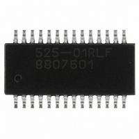
ICS525-01RLF IDT, Integrated Device Technology Inc, ICS525-01RLF Datasheet - Page 5

ICS525-01RLF
Manufacturer Part Number
ICS525-01RLF
Description
IC CLK USER CONFIGURABLE 28-SSOP
Manufacturer
IDT, Integrated Device Technology Inc
Series
OSCaR™r
Type
Clock Generator, Fanout Distributionr
Datasheet
1.ICS525R-02LF.pdf
(9 pages)
Specifications of ICS525-01RLF
Pll
Yes with Bypass
Input
Clock, Crystal
Output
CMOS
Number Of Circuits
1
Ratio - Input:output
1:2
Differential - Input:output
No/No
Frequency - Max
160MHz
Divider/multiplier
Yes/No
Voltage - Supply
3 V ~ 5.5 V
Operating Temperature
0°C ~ 70°C
Mounting Type
Surface Mount
Package / Case
28-SSOP
Frequency-max
160MHz
Number Of Elements
1
Supply Current
8mA
Pll Input Freq (min)
2MHz
Pll Input Freq (max)
50MHz
Operating Supply Voltage (typ)
3.3/5V
Operating Temp Range
0C to 70C
Package Type
QSOP
Output Frequency Range
3 to 160MHz
Operating Supply Voltage (min)
3V
Operating Supply Voltage (max)
5.5V
Operating Temperature Classification
Commercial
Pin Count
28
Lead Free Status / RoHS Status
Lead free / RoHS Compliant
Other names
525-01RLF
800-1047
800-1047-5
800-1047
800-1047
800-1047-5
800-1047
Available stocks
Company
Part Number
Manufacturer
Quantity
Price
Company:
Part Number:
ICS525-01RLF
Manufacturer:
LTC
Quantity:
221
Company:
Part Number:
ICS525-01RLF
Manufacturer:
ICS
Quantity:
18
Part Number:
ICS525-01RLF
Manufacturer:
IDT
Quantity:
20 000
Part Number:
ICS525-01RLFT
Manufacturer:
TNTEGRATED
Quantity:
20 000
MDS 525-01/02 T
Absolute Maximum Ratings
The dividers are expressed as integers. For example, if a 66.66 MHz output on CLK1 is desired from a
14.31818 MHz input, the VCO divider word (VDW) should be 276, with an output divide (OD) of 2. In this
example, R6:R0 is 0111011, V8:V0 is 100010100 and S2:S0 is 001. Since all of these inputs have pull-up
resistors, it is only necessary to ground the zero pins, namely V7, V6, V5, V3, V1, V0, R6, R2, S2, and S1.
To determine the best combination of VCO, reference, and output divide, use the ICS525 Calculator on our
web site: www.idt.com. The online form is easy to use and quickly shows you up to three options for these
settings. Alternately, you may send an e-mail to www.idt.com/go/clockhelp.
Stresses above the ratings listed below can cause permanent damage to the ICS525-01/02. These ratings,
which are standard values for IDT commercially rated parts, are stress ratings only. Functional operation of
the device at these or any other conditions above those indicated in the operational sections of the
specifications is not implied. Exposure to absolute maximum rating conditions for extended periods can
affect product reliability. Electrical parameters are guaranteed only over the recommended operating
temperature range.
Supply Voltage, VDD
All Inputs and Outputs
Ambient Operating Temperature, Commercial
Ambient Operating Temperature, Industrial
Storage Temperature
Junction Temperature
Soldering Temperature
Integrated Device Technology, Inc.
Item
5
●
www.idt.com
7 V
-0.5 V to VDD+0.5 V
0 to +70 C
-40 to +85 C
-65 C to 150 C
125 C
260 C (max. of 10 seconds)
OSCaR
TM
Rating
User Configurable Clock
Revision 081810
ICS525-01/02


