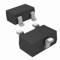
MAX7375AXR425+T Maxim Integrated Products, MAX7375AXR425+T Datasheet - Page 4

MAX7375AXR425+T
Manufacturer Part Number
MAX7375AXR425+T
Description
IC OSCILLATOR SIL SC70-3
Manufacturer
Maxim Integrated Products
Type
Oscillator, Siliconr
Datasheet
1.MAX7375AXR425T.pdf
(7 pages)
Specifications of MAX7375AXR425+T
Frequency
4.19MHz
Voltage - Supply
2.7 V ~ 5.5 V
Operating Temperature
-40°C ~ 125°C
Package / Case
SC-70-3, SOT-323-3
Lead Free Status / RoHS Status
Lead free / RoHS Compliant
Count
-
Other names
MAX7375AXR425+T
MAX7375AXR425+TTR
MAX7375AXR425+TTR
The MAX7375 is a replacement for ceramic resonators,
crystals, and crystal oscillator modules as the clock
source for microcontrollers and UARTs in 3V, 3.3V, and
5V applications. The MAX7375 is an integrated oscilla-
tor, supplied at specific frequencies just like crystals
and resonators. A variety of popular standard frequen-
cies are available. No external components are
required for setting or adjusting the frequency.
The MAX7375 has been designed for use in systems
with nominal supply voltages of 3V, 3.3V, or 5V and is
specified for operation with supply voltages in the 2.7V
to 5.5V range. Operation outside this range is not guar-
anteed. See the Absolute Maximum Ratings table for
limit values of power-supply and pin voltages.
The clock output is a push-pull configuration and is
capable of driving a ground-connected 1kΩ load or a
3-Pin Silicon Oscillator
(V+ = 5V, T
4
_______________________________________________________________________________________
A
SC70
= +25°C, C
PIN
1
2
3
CLOCK OUTPUT WAVEFORM
L
Detailed Description
= 10pF, 8MHz output, unless otherwise noted.)
WITH C
40ns/div
L
= 50pF
Supply Voltages
CLOCK
NAME
GND
V+ = 3.3V
V+
MAX7375 toc10
Typical Operating Characteristics (continued)
Oscillator
CLOCK
1V/div
Positive Supply Voltage
Clock output. Output is push-pull.
Ground
positive supply connected 500Ω load to within 300mV
of either supply rail. The clock output remains stable
over the full operating voltage range and does not gen-
erate short output cycles during either power on or
power off. A typical startup characteristic is shown in
the Typical Operating Characteristics section.
The MAX7375’s jitter performance is given in the
Electrical Characteristics table as a peak-to-peak value
obtained by observing the output of the MAX7375 for
20s with a 500MHz oscilloscope. Jitter measurements
are approximately proportional to the period of the out-
put frequency of the device. Thus, a 4MHz part has
approximately twice the jitter value of an 8MHz part.
The jitter performance of all clock sources degrades in
the presence of mechanical and electrical interference.
The MAX7375 is relatively immune to vibration, shock,
and EMI influences and thus provides a considerably
more robust clock source than crystal- or ceramic-res-
onator-based oscillator circuits.
CLOCK OUTPUT WAVEFORM
WITH C
40ns/div
FUNCTION
L
= 100pF
V+ = 3.3V
MAX7375 toc11
Pin Description
CLOCK
1V/div
Output Jitter


