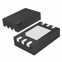
LTC6991HDCB#TRPBF Linear Technology, LTC6991HDCB#TRPBF Datasheet - Page 12

LTC6991HDCB#TRPBF
Manufacturer Part Number
LTC6991HDCB#TRPBF
Description
IC TIMERBLOX OSCILLATOR 6-DFN
Manufacturer
Linear Technology
Datasheet
1.LTC6991CDCBTRMPBF.pdf
(24 pages)
Specifications of LTC6991HDCB#TRPBF
Frequency
*
Voltage - Supply
*
Current - Supply
135µA
Operating Temperature
*
Package / Case
6-WFDFN Exposed Pad
Count
*
Lead Free Status / RoHS Status
Lead free / RoHS Compliant
Available stocks
Company
Part Number
Manufacturer
Quantity
Price
operaTion
LTC6991
Changing DIVCODE After Start-Up
Following start-up, the A/D converter will continue
monitoring V
to DIVCODE changes in less than one cycle.
The output may have an inaccurate pulse width during the
frequency transition. But the transition will be glitch-free
and no high or low pulse can be shorter than the mas-
ter clock period. A digital filter is used to guarantee the
DIVCODE has settled to a new value before making changes
to the output.
Start-Up Time
When power is first applied, the power-on reset (POR)
circuit will initiate the start-up time, t
is held low during this time. The typical value for t
ranges from 0.5ms to 8ms depending on the master oscil-
lator frequency (independent of N
During start-up, the DIV pin A/D converter must determine
the correct DIVCODE before the output is enabled. The
t
t
200mV/DIV
DIVCODE
START(TYP)
1V/DIV
OUT
DIV
V
R
< 500 • t
+
Figure 5. DIVCODE Change from 1 to 0
SET
= 3.3V
DIV
= 500 • t
= 200k
for changes. The LTC6991 will respond
MASTER
MASTER
10ms/DIV
< t
OUT
DIV
):
START
6991 F05
. The OUT pin
START
start-up time may increase if the supply or DIV pin volt-
ages are not stable. For this reason, it is recommended to
minimize the capacitance on the DIV pin so it will properly
track V
Start-Up Behavior
When first powered up, the output is held low. If the po-
larity is set for non-inversion (POL = 0) and the output is
enabled (RST = 0) at the end of the start-up time, OUT will
begin oscillating. If the output is being reset (RST = 1) at
the end of the start-up time, the first pulse will be skipped.
Subsequent pulses will also be skipped until RST = 0.
In inverted operation (POL = 1), the start-up sequence is
similar. However, the LTC6991 does not know the correct
DIVCODE setting when first powered up, so the output
defaults low. At the end of t
recognized and OUT goes high (inactive) because POL = 1.
If RST = 1 (inactive) then OUT will quickly fall after a single
t
the output is held in reset and remains high.
Figures 7 to 10 detail the four possible start-up sequences.
MASTER
1V/DIV
1V/DIV
+
OUT
. Less than 100pF will not affect performance.
cycle. If RST = 0 at the end of the start-up time,
V
+
V
DIVCODE = 0
R
+
SET
= 2.5V
= 50k
500µs
Figure 6. Typical Start-Up
250µs/DIV
START
, the value of DIVCODE is
6991 F06
6991f


