DS1744WP-120+ Maxim Integrated Products, DS1744WP-120+ Datasheet - Page 15
DS1744WP-120+
Manufacturer Part Number
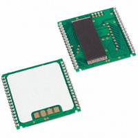
DS1744WP-120+
Description
IC RTC RAM Y2K 3.3V 120NS 34-PCM
Manufacturer
Maxim Integrated Products
Type
Clock/Calendar/NVSRAM/Y2Kr
Datasheet
1.DS1744W-120.pdf
(16 pages)
Specifications of DS1744WP-120+
Memory Size
256K (32K x 8)
Time Format
HH:MM:SS (24 hr)
Date Format
YY-MM-DD-dd
Interface
Parallel
Voltage - Supply
3 V ~ 3.6 V
Operating Temperature
0°C ~ 70°C
Mounting Type
Surface Mount
Package / Case
34-PowerCap™ Module
Function
Clock/Calendar/NV Timekeeping RAM
Rtc Memory Size
32768 Byte
Supply Voltage (max)
3.63 V
Supply Voltage (min)
2.97 V
Maximum Operating Temperature
+ 70 C
Minimum Operating Temperature
0 C
Mounting Style
Through Hole
Rtc Bus Interface
Parallel
Supply Current
75 mA
Lead Free Status / RoHS Status
Lead free / RoHS Compliant


AC TEST CONDITIONS
Output Load: 50pF + 1TTL Gate
Input Pulse Levels: 0 to 3.0V
Timing Measurement Reference Levels:
Input Pulse Rise and Fall Times: 5ns
NOTES:
1) Voltages are referenced to ground.
2) Typical values are at +25C and nominal supplies.
3) Outputs are open.
4) Battery switchover occurs at the lower of either the battery terminal voltage or V
5) Data-retention time is at +25C.
6) Each DS1744 has a built-in switch that disconnects the lithium source until the user first applies V
7) RTC modules (DIP) can be successfully processed through conventional wave-soldering techniques as
8) t
9) t
10) t
PACKAGE INFORMATION
For the latest package outline information and land patterns, go to www.maxim-ic.com/packages.
in the package code indicates RoHS status only. Package drawings may show a different suffix character, but the drawing
pertains to the package regardless of RoHS status.
PACKAGE TYPE
The expected t
in the absence of V
long as temperature exposure to the lithium energy source contained within does not exceed +85C.
Post-solder cleaning with water-washing techniques is acceptable, provided that ultrasonic vibration is
not used.
In addition, for the PowerCap:
AH1
AH2
WC
34 PWRCP
Input: 1.5V
Output: 1.5V
a. ) Maxim recommends that PowerCap module bases experience one pass through solder reflow
b.) Hand soldering and touch-up: Do not touch or apply the soldering iron to leads for more than 3
, t
, t
= 200ns.
28 EDIP
DH1
DH2
oriented with the label side up (“live-bug”).
seconds. To solder, apply flux to the pad, heat the lead frame pad, and apply solder. To remove
the part, apply flux, heat the lead frame pad until the solder reflows, and use a solder wick to
remove solder.
are measured from WE going high.
are measured from CE going high.
DR
is defined for DIP modules and assembled PowerCap modules as a cumulative time
CC
starting from the time power is first applied by the user.
PACKAGE CODE
MDF28+3
PC2+2
DS1744/DS1744P Y2K-Compliant, Nonvolatile Timekeeping RAMs
15 of 16
DOCUMENT NO.
21-0245
21-0246
LAND PATTERN NO.
Note that a “+”, “#”, or “-”
PF
.
—
—
CC
.
Related parts for DS1744WP-120+
Image
Part Number
Description
Manufacturer
Datasheet
Request
R

Part Number:
Description:
IC RTC RAM Y2K 3.3V 120NS 34-PCM
Manufacturer:
Maxim Integrated Products
Datasheet:
Part Number:
Description:
IC RTC RAM Y2K 3.3V 120NS 34-PCM
Manufacturer:
Maxim Integrated Products
Datasheet:

Part Number:
Description:
Real Time Clock
Manufacturer:
Maxim Integrated Products
Datasheet:

Part Number:
Description:
IC RTC RAM Y2K 3.3V 120NS 28EDIP
Manufacturer:
Maxim Integrated Products
Datasheet:
Part Number:
Description:
IC RTC RAM Y2K 3.3V 120NS 28EDIP
Manufacturer:
Maxim Integrated Products
Datasheet:
Part Number:
Description:
IC RTC RAM Y2K 3.3V 120NS 28EDIP
Manufacturer:
Maxim Integrated Products
Datasheet:
Part Number:
Description:
IC RTC RAM Y2K 3.3V 120NS 28EDIP
Manufacturer:
Maxim Integrated Products
Datasheet:
Part Number:
Description:
MAX7528KCWPMaxim Integrated Products [CMOS Dual 8-Bit Buffered Multiplying DACs]
Manufacturer:
Maxim Integrated Products
Datasheet:
Part Number:
Description:
Single +5V, fully integrated, 1.25Gbps laser diode driver.
Manufacturer:
Maxim Integrated Products
Datasheet:
Part Number:
Description:
Single +5V, fully integrated, 155Mbps laser diode driver.
Manufacturer:
Maxim Integrated Products
Datasheet:
Part Number:
Description:
VRD11/VRD10, K8 Rev F 2/3/4-Phase PWM Controllers with Integrated Dual MOSFET Drivers
Manufacturer:
Maxim Integrated Products
Datasheet:
Part Number:
Description:
Highly Integrated Level 2 SMBus Battery Chargers
Manufacturer:
Maxim Integrated Products
Datasheet:
Part Number:
Description:
Current Monitor and Accumulator with Integrated Sense Resistor; ; Temperature Range: -40°C to +85°C
Manufacturer:
Maxim Integrated Products
Part Number:
Description:
TSSOP 14/A°/RS-485 Transceivers with Integrated 100O/120O Termination Resis
Manufacturer:
Maxim Integrated Products
Part Number:
Description:
TSSOP 14/A°/RS-485 Transceivers with Integrated 100O/120O Termination Resis
Manufacturer:
Maxim Integrated Products