DS1554WP-120+ Maxim Integrated Products, DS1554WP-120+ Datasheet - Page 17
DS1554WP-120+
Manufacturer Part Number
DS1554WP-120+
Description
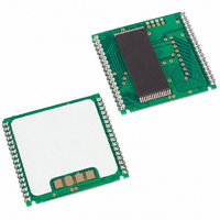
IC RTC RAM Y2K 3.3V 120NS 34-PCM
Manufacturer
Maxim Integrated Products
Type
Clock/Calendar/NVSRAM/Y2Kr
Datasheet
1.DS1554P-70.pdf
(18 pages)
Specifications of DS1554WP-120+
Memory Size
256K (32K x 8)
Time Format
HH:MM:SS (24 hr)
Date Format
YY-MM-DD-dd
Interface
Parallel
Voltage - Supply
3 V ~ 3.6 V
Operating Temperature
0°C ~ 70°C
Mounting Type
Surface Mount
Package / Case
34-PowerCap™ Module
Lead Free Status / RoHS Status
Lead free / RoHS Compliant


AC TEST CONDITIONS
Output Load: 50 pF + 1TTL Gate
Input Pulse Levels: 0 to 3.0V
Timing Measurement Reference Levels:
Input Pulse Rise and Fall Times: 5 ns
NOTES:
1) Voltage referenced to ground.
2) Typical values are at +25C and nominal supplies.
3) Outputs are open.
4) Battery switchover occurs at the lower of either the battery voltage or V
5) The
6) Data-retention time is at +25C.
7) Each DS1554 has a built-in switch that disconnects the lithium source until V
8) RTC modules (DIP) can be successfully processed through conventional wave-soldering techniques
9) t
10) t
11)
PACKAGE INFORMATION
For the latest package outline information and land patterns, go to
in the package code indicates RoHS status only. Package drawings may show a different suffix character, but the drawing
pertains to the package regardless of RoHS status.
PACKAGE TYPE
user. The expected t
absence of V
as long as temperature exposure to the lithium energy source contained within does not exceed
+85C. Post-solder cleaning with water-washing techniques is acceptable, provided that ultrasonic
vibration is not used.
In addition, for the PowerCap:
a. Maxim recommends that PowerCap Module bases experience one pass through solder reflow
b. Hand soldering and touch-up: Do not touch or apply the soldering iron to leads for more than
t
AH1
AH2
WC
34 PWRCP
= 200ns.
Input: 1.5V
Output: 1.5V
oriented with the label side up (“live-bug”).
3 seconds. To solder, apply flux to the pad, heat the lead frame pad and apply solder. To remove
the part, apply flux, heat the lead frame pad until the solder reflow and use a solder wick to
remove solder.
, t
, t
32 EDIP
IRQ
DH1
DH2
/FT and RST outputs are open drain.
are measured from WE going high.
are measured from CE going high.
CC
starting from the time power is first applied by the user.
DR
is defined for DIP modules and PowerCap modules as a cumulative time in the
PACKAGE CODE
MDF32+1
PC2+2
DS1554 256k, Nonvolatile, Y2K-Compliant Timekeeping RAM
17 of 18
www.maxim-ic.com/packages
DOCUMENT NO.
21-0245
21-0246
PF
.
LAND PATTERN NO.
CC
.
Note that a “+”, “#”, or “-”
is first applied by the
—
—
Related parts for DS1554WP-120+
Image
Part Number
Description
Manufacturer
Datasheet
Request
R

Part Number:
Description:
IC RTC RAM Y2K 3.3V 120NS 34-PCM
Manufacturer:
Maxim Integrated Products
Datasheet:
Part Number:
Description:
IC RTC RAM Y2K 3.3V 120NS 34-PCM
Manufacturer:
Maxim Integrated Products
Datasheet:

Part Number:
Description:
Real Time Clock
Manufacturer:
Maxim Integrated Products
Datasheet:

Part Number:
Description:
IC RTC RAM Y2K 3.3V 120NS 32EDIP
Manufacturer:
Maxim Integrated Products
Datasheet:
Part Number:
Description:
IC RTC RAM Y2K 3.3V 120NS 32EDIP
Manufacturer:
Maxim Integrated Products
Datasheet:
Part Number:
Description:
IC RTC RAM Y2K 3.3V 120NS 32EDIP
Manufacturer:
Maxim Integrated Products
Datasheet:
Part Number:
Description:
IC RTC RAM Y2K 3.3V 120NS 32EDIP
Manufacturer:
Maxim Integrated Products
Datasheet:
Part Number:
Description:
MAX7528KCWPMaxim Integrated Products [CMOS Dual 8-Bit Buffered Multiplying DACs]
Manufacturer:
Maxim Integrated Products
Datasheet:
Part Number:
Description:
Single +5V, fully integrated, 1.25Gbps laser diode driver.
Manufacturer:
Maxim Integrated Products
Datasheet:
Part Number:
Description:
Single +5V, fully integrated, 155Mbps laser diode driver.
Manufacturer:
Maxim Integrated Products
Datasheet:
Part Number:
Description:
VRD11/VRD10, K8 Rev F 2/3/4-Phase PWM Controllers with Integrated Dual MOSFET Drivers
Manufacturer:
Maxim Integrated Products
Datasheet:
Part Number:
Description:
Highly Integrated Level 2 SMBus Battery Chargers
Manufacturer:
Maxim Integrated Products
Datasheet:
Part Number:
Description:
Current Monitor and Accumulator with Integrated Sense Resistor; ; Temperature Range: -40°C to +85°C
Manufacturer:
Maxim Integrated Products
Part Number:
Description:
TSSOP 14/A°/RS-485 Transceivers with Integrated 100O/120O Termination Resis
Manufacturer:
Maxim Integrated Products
Part Number:
Description:
TSSOP 14/A°/RS-485 Transceivers with Integrated 100O/120O Termination Resis
Manufacturer:
Maxim Integrated Products