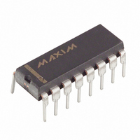
DS1615 Maxim Integrated Products, DS1615 Datasheet - Page 13

DS1615
Manufacturer Part Number
DS1615
Description
IC RECORDER TEMP 5V 16-DIP
Manufacturer
Maxim Integrated Products
Type
Temperature Recorderr
Datasheet
1.DS1615.pdf
(24 pages)
Specifications of DS1615
Memory Size
32B
Time Format
HH:MM:SS (12/24 hr)
Date Format
YY-MM-DD-dd
Interface
3-Wire Serial
Voltage - Supply
4 V ~ 5.5 V
Operating Temperature
-40°C ~ 85°C
Mounting Type
Through Hole
Package / Case
16-DIP (0.300", 7.62mm)
Lead Free Status / RoHS Status
Contains lead / RoHS non-compliant
Available stocks
Company
Part Number
Manufacturer
Quantity
Price
Part Number:
DS1615S
Manufacturer:
MAXIM/美信
Quantity:
20 000
TLIE - Temperature Low Interrupt Enable - When set to a logic 1, this bit permits the Temperature Low
Flag (TLF) in the Status register to assert
initiate the
THIE - Temperature High Interrupt Enable - When set to a logic 1, this bit permits the Temperature High
Flag (THF) in the Status register to assert
initiate the
AIE - Alarm Interrupt Enable - When set to a logic 1, this bit permits the Alarm Flag (ALMF) in the
Status register to assert
signal.
STATUS REGISTER
TR - Temperature Ready This bit indicates the status of the temperature value in the Current Temperature
register after the Read Temperature command has been executed. When this bit is a logic 1, the DS1615
has completed the temperature measurement and has written a valid value to the Current Temperature
register. When this bit is a logic 0, the temperature measurement has not been completed. This bit is
cleared to 0 when the Read Temperature command is sent.
MEM CLR - Memory Cleared This bit indicates that the datalog memory, histogram memory,
Temperature Alarm, Current Samples, Start Time Stamp, Start Delay, and Sample Rate registers are all
cleared to zero. MEM CLR is cleared to 0 when a datalog mission is started (i.e., MIP = 1).
MIP - Mission in Progress This bit indicates the sampling status of the DS1615. If MIP is a logic 1, the
device is currently on a mission in which it is operating in the datalogging mode. The MIP bit is changed
to a logic 1 immediately following 1) the writing of a non-zero value to the Sample Rate register when
the SE bit is a 0 or 2) a 0.5 second pulse on the
value AND the SE bit is a 1.
If MIP is a logic 0, the DS1615 is not currently in datalogging mode. The MIP bit transitions from a
logic 1 to a logic 0 whenever datalogging is stopped. Datalogging is stopped when the DS1615 is cleared
via the clear bit and clear instruction or when any of the RTC or Control registers (with the exception of
the Status register) are written to during a mission. The MIP bit can also be written to a logic 0 by the
end user to stop datalogging. It cannot, however, be written to a logic 1.
SIP - Sample in Progress This bit indicates that the DS1615 is currently in the process of acquiring a
temperature sample. When the SIP bit is 0, a temperature conversion is not currently in process and the
next conversion will not begin for at least 250 ms. When the SIP bit is a 1, a temperature conversion is in
progress and no registers or memory locations should be read or written. The SIP bit will be a 1 for a
maximum of 750 ms.
LOBAT - Low Battery Flag - This bit reflects the status of the backup power source connected to the
V
MSb
BAT
TR
pin. A logic one for this bit indicates an exhausted lithium energy source.
INT
INT
MEMCL
signal.
signal.
INT
. When the AIE bit is set to logic 0, the ALMF bit does not initiate the
MIP
INT
INT
SIP
. When the THIE bit is set to logic 0, the THF bit does not
. When the TLIE bit is set to logic 0, the TLF bit does not
ST
13 of 24
pin if the Sample Rate register contains a non-zero
LOBAT
TLF
THF
ALMF
LSb
INT


