3-647134-1 TE Connectivity, 3-647134-1 Datasheet - Page 3
3-647134-1
Manufacturer Part Number
3-647134-1
Description
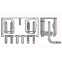
11P MTA156 SHRD HDR ASSY LF
Manufacturer
TE Connectivity
Specifications of 3-647134-1
Connector Type
Header
Product Line
MTA-156
Pcb Mounting Orientation
Right Angle
Right Angle Bending Side
Rear
Pcb Mount Retention
Without
Mating Connector Lock
Without
Four Points Of Contact
Without
Shrouded
Yes
Mounting Ears
Without
Post Size (mm [in])
1.14 [.045]
Panel Mount Retention
Without
Current Rating (a)
7
Voltage Rating (vac)
600
Solder Tail Contact Plating
Bright Tin
Termination Post Length (mm [in])
3.18 [0.125]
Number Of Positions
11
Centerline (mm [in])
3.96 [0.156]
Narrow
No
Post Number(s) Omitted
None
Contact Type
Pin
Contact Shape
Square
Contact Plating, Mating Area, Material
Gold (30) or (30) Total Gold Flash over Palladium Nickel
Contact Base Material
Copper Alloy
Connector Style
Plug
Housing Color
Black
Mating Alignment
Without
Ul Flammability Rating
UL 94V-0
Housing Material
Polyester
Backwall/post Interruption(s)
Without
Rohs/elv Compliance
RoHS compliant, ELV compliant
Lead Free Solder Processes
Wave solder capable to 240°C
Rohs/elv Compliance History
Always was RoHS compliant
Applies To
Printed Circuit Board
Application Use
Wire-to-Board


Termination tensile strength,
perpendicular, unmated.
Vibration, sinusoidal.
Vibration, random.
Mechanical shock.
Durability.
Mating force.
Unmating force.
Thermal shock.
Rev J
Test Description
No discontinuities of 1 microsecond
or longer duration.
See Note.
No discontinuities of 1 microsecond
or longer duration.
See Note.
No discontinuities of 1 microsecond
or longer duration.
See Note.
See Note.
Standard contact: 1.75 pounds
maximum per contact.
High force contact: 6 pounds
maximum per contact.
Gold contact: 1.25 pounds
maximum per contact.
Standard contact: .2 pound
minimum per contact.
High force contact: .7 pound
minimum per contact.
Gold contact: .1 pound minimum
per contact.
See Note.
Wire Size
AWG
26
24
22
20
18
Figure 1 (continued)
ENVIRONMENTAL
Requirement
Pounds Minimum
Slot Tensile
1.3
1.3
3.4
4.0
4.6
TE Spec 109-16.
Determine slot tensile strength by
pulling perpendicular to terminated
wire at maximum rate of 1 inch per
minute.
See Figure 5.
TE Spec 109-21-1.
Subject mated samples to 10-55-10
Hz traversed in 1 minute with 0.06
inch maximum total excursion. Two
hours in each of 3 mutually
perpendicular planes.
See Figure 6.
TE Spec 109-21-7.
Subject mated samples to 3.15 G's
rms between 5-500 Hz. Fifteen
minutes in each of 3 mutually
perpendicular planes.
See Figure 6.
TE Spec 109-26-1.
Subject mated samples to 50 G's
half-sine shock pulses of 11
milliseconds duration. Three shocks
in each direction applied along 3
mutually perpendicular planes, 18
total shocks.
See Figure 6.
TE Spec 109-27.
With header mounted in fixture,
manually mate and unmate
samples for 25 cycles.
TE Spec 109-42, Condition A.
Measure force necessary to mate
samples with header at maximum
rate of .5 inch per minute. Calculate
force per contact.
TE Spec 109-42, Condition A.
Measure force necessary to unmate
samples from header at maximum
rate of .5 inch per minute. Calculate
force per contact.
TE Spec 109-22.
Subject mated samples to 25 cycles
between -55 and 105° C.
Procedure
108-1051
3 of 10
Related parts for 3-647134-1
Image
Part Number
Description
Manufacturer
Datasheet
Request
R

Part Number:
Description:
Manufacturer:
TE Connectivity
Datasheet:

Part Number:
Description:
Headers & Wire Housings 64 MODII HDR DRST B/ 1000
Manufacturer:
TE Connectivity
Datasheet:

Part Number:
Description:
Conn Unshrouded Header HDR 64 POS 2.54mm Solder ST Thru-Hole
Manufacturer:
Tyco Electronics

Part Number:
Description:
HEAT SHRINK TUBING
Manufacturer:
QUALTEK ELECTRONICS
Datasheet:
Part Number:
Description:
HEAT SHRINK TUBING
Manufacturer:
QUALTEK ELECTRONICS
Datasheet:

Part Number:
Description:
Conn IDC Connector F 6 POS 2.54mm IDT RA Cable Mount Loose Piece
Manufacturer:
TE Connectivity
Datasheet:

Part Number:
Description:
Conn IDC Connector F 6 POS 3.96mm IDT RA Cable Mount
Manufacturer:
TE Connectivity
Datasheet:
Part Number:
Description:
Conn IDC Connector F 6 POS 3.96mm IDT RA Cable Mount
Manufacturer:
TE Connectivity
Datasheet:

Part Number:
Description:
Conn IDC Connector F 6 POS 2.54mm IDT RA Cable Mount Loose Piece
Manufacturer:
TE Connectivity
Datasheet:
Part Number:
Description:
Conn IDC Connector F 6 POS 3.96mm IDT RA Cable Mount
Manufacturer:
TE Connectivity
Datasheet:

Part Number:
Description:
Manufacturer:
TE Connectivity
Datasheet:

Part Number:
Description:
WIRE-BOARD CONN RECEPTACLE, 6POS, 2.54MM
Manufacturer:
TE Connectivity
Datasheet:

Part Number:
Description:
PLUG & SOCKET CONNECTOR, PLUG, 6POS, 3MM
Manufacturer:
TE Connectivity
Datasheet:

Part Number:
Description:
Manufacturer:
TE Connectivity
Datasheet:

Part Number:
Description:
STACKING CONNECTOR, PLUG, 440POS, 0.5MM
Manufacturer:
TE Connectivity
Datasheet: