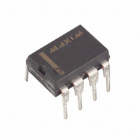
MAX1240ACPA+ Maxim Integrated Products, MAX1240ACPA+ Datasheet - Page 8

MAX1240ACPA+
Manufacturer Part Number
MAX1240ACPA+
Description
IC ADC 12BIT SERIAL 8-DIP
Manufacturer
Maxim Integrated Products
Datasheet
1.MAX1241BCSA.pdf
(15 pages)
Specifications of MAX1240ACPA+
Number Of Bits
12
Sampling Rate (per Second)
73k
Data Interface
MICROWIRE™, QSPI™, Serial, SPI™
Number Of Converters
1
Power Dissipation (max)
727mW
Voltage Supply Source
Single Supply
Operating Temperature
0°C ~ 70°C
Mounting Type
Through Hole
Package / Case
8-DIP (0.300", 7.62mm)
Lead Free Status / RoHS Status
Lead free / RoHS Compliant
+2.7V, Low-Power,
12-Bit Serial ADCs in 8-Pin SO
The MAX1240/MAX1241 use an input track/hold (T/H)
and successive-approximation register (SAR) circuitry
to convert an analog input signal to a digital 12-bit out-
put. No external-hold capacitor is needed for the T/H.
Figure 3 shows the MAX1240/MAX1241 in its simplest
configuration. The MAX1240/MAX1241 convert input
signals in the 0V to V
acquisition time. The MAX1240’s internal reference is
trimmed to 2.5V, while the MAX1241 requires an external
reference. Both devices accept voltages from 1.0V to
V
(SCLK, CS, and DOUT) and provides an easy interface
to microprocessors (µPs).
The MAX1240/MAX1241 have two modes: normal and
shutdown. Pulling SHDN low shuts the device down and
reduces supply current below 10µA (V
pulling SHDN high or leaving it open puts the device
into operational mode. Pulling CS low initiates a conver-
sion. The conversion result is available at DOUT in
unipolar serial format. The serial data stream consists
of a high bit, signaling the end of conversion (EOC), fol-
lowed by the data bits (MSB first).
Figure 4 illustrates the sampling architecture of the ana-
log-to-digital converter’s (ADC’s) comparator. The full-
scale input voltage is set by the voltage at REF.
In track mode, the analog signal is acquired and stored
in the internal hold capacitor. In hold mode, the T/H
switch opens and maintains a constant input to the
ADC’s SAR section.
8
Figure 3. Operational Diagram
_______________Detailed Description
+2.7V to +3.6V*
DD
(MAX1241 ONLY)
ANALOG INPUT
_______________________________________________________________________________________
. The serial interface requires only three digital lines
SHUTDOWN
REFERENCE
0V TO V
INPUT
INPUT
REF
4.7μF
0.1μF
C**
1
2
3
4
REF
V
AIN
SHDN
REF
DD
range in 9µs, including T/H
MAX1240
MAX1241
Converter Operation
DOUT
SCLK
GND
**
CS
*
V
4.7μF (MAX1240)
0.1μF (MAX1241)
DD,MAX
8
7
6
5
DD
Analog Input
= +5.25V (MAX1241)
≤ 3.6V
Track/Hold
SERIAL
INTERFACE
)
, while
During acquisition, the analog input (AIN) charges
capacitor C
interval. At this instant, the T/H switches the input side
of C
sents a sample of the input, unbalancing node ZERO at
the comparator’s input.
In hold mode, the capacitive digital-to-analog converter
(DAC) adjusts during the remainder of the conversion
cycle to restore node ZERO to 0V within the limits of 12-
bit resolution. This action is equivalent to transferring a
charge from C
DAC, which in turn forms a digital representation of the
analog input signal. At the conversion’s end, the input
side of C
charges to the input signal again.
The time required for the T/H to acquire an input signal
is a function of how quickly its input capacitance is
charged. If the input signal’s source impedance is high,
the acquisition time lengthens and more time must be
allowed between conversions. The acquisition time
(t
the signal, and is also the minimum time needed for the
signal to be acquired. Acquisition time is calculated by:
where R
ance, and t
ances below 1kΩ do not significantly affect the ADC’s
AC performance.
Higher source impedances can be used if a 0.01µF
capacitor is connected to the analog input. Note that
the input capacitor forms an RC filter with the input
source impedance, limiting the ADC’s input signal
bandwidth.
Figure 4. Equivalent Input Circuit
ACQ
GND
AIN
HOLD
) is the maximum time the device takes to acquire
IN
REF
TRACK INPUT
to GND. The retained charge on C
HOLD
= 9kΩ, R
HOLD
ACQ
HOLD
t
ACQ
12-BIT CAPACITIVE DAC
HOLD
is never less than 1.5µs. Source imped-
. Bringing CS low ends the acquisition
switches back to AIN, and C
C
SWITCH
= 9(R
C
S
-
16pF
HOLD
TRACK
to the binary-weighted capacitive
= the input signal’s source imped-
+
S
+ R
R
9k
IN
HOLD
ZERO
IN
) x 16pF
AT THE SAMPLING INSTANT,
THE INPUT SWITCHES FROM
AIN TO GND.
COMPARATOR
HOLD
repre-
HOLD


