5536254-6 TE Connectivity, 5536254-6 Datasheet

140,VT,RC,BD,BD,30AU,125ST

5536254-6

Manufacturer Part Number
5536254-6
Description
140,VT,RC,BD,BD,30AU,125ST
Manufacturer
TE Connectivity
Datasheets

Specifications of 5536254-6

Product Type
Connector
Mount Angle
Vertical
Termination Method To Pc Board
Through Hole - Solder
Pcb Mount Retention
Without
Guides
Without
Flame Retardant
Yes
Bus Bar Material
Phosphor Bronze
Tail Length (mm [in])
3.18 [0.125]
Bus Bar Mating Area Plating
Gold (30)
Bus Bar Termination Area Plating
Matte Tin with Nickel underplated
Number Of Positions
140
Signal Contact Material
Phosphor Bronze
Signal Contact Mating Area Plating
Gold (30)
Signal Contact Termination Area Plating
Matte Tin with Nickel underplated
Connector Style
Receptacle
Housing Material
High Temperature Thermoplastic
Stack Height (mm [in])
10.92 [0.430], 18.75 [0.738]
Rohs/elv Compliance
RoHS compliant, ELV compliant
Lead Free Solder Processes
Wave solder capable to 240°C, Wave solder capable to 260°C, Wave solder capable to 265°C
Rohs/elv Compliance History
Always was RoHS compliant

Available stocks

Company
Part Number
Manufacturer
Quantity
Price
Part Number:
5536254-6
Manufacturer:
TE Connectivity AMP Connectors
Quantity:
346
1.
1.1.
1.2.
2.
2.1.
3.
3.1.
3.2.
3.3.
©2011 Tyco Electronics Corporation,
a TE Connectivity Ltd. Company
All Rights Reserved
TE logo is a trademark.
SCOPE
Content
This specification covers perform ance, tests and quality requirem ents for TE Connectivity (TE) Micro-
Strip board to board right angle and vertical connector fam ily. These assem blies accom m odate a variety
of printed circuit board thicknesses. Plug assem blies are loaded with .015 inch square m ale Micro-Strip
contacts which m ate with receptacle assem blies loaded with fem ale Micro-Strip contacts.
Qualification
W hen tests are perform ed on subject product line, procedures specified in 109 Series Test
Specifications shall be used. All inspections shall be perform ed using applicable inspection plan and
product drawing.
APPLICABLE DOCUM ENTS
The following docum ents form a part of this specification to the extent specified herein. Unless
otherwise specified, latest edition of the docum ent applies. In the event of conflict between
requirem ents of this specification and product drawing, product drawing shall take precedence. In the
event of conflict between requirem ents of this specification and referenced docum ents, this specification
shall take precedence.
TE Docum ents
!
!
!
!
REQUIREM ENTS
Design and Construction
Product shall be of design, construction and physical dim ensions specified on applicable product
drawing.
Materials
!
!
Ratings
!
!
!
109-1: General Requirem ents for Test Specifications
109 Series: Test Specifications as indicated in Figure 1
114-11005: Application Specification
501-235: Test Report
Contact: Phosphor bronze or beryllium copper, selective gold over nickel plating
Housing: High tem perature therm oplastic, liquid crystal polym er
Voltage: 30 volts alternating current
Current: See Figure 2 for applicable current carrying capability
Tem perature: -65 to 125 C
| Indicates change
*Trademark
Product
Specification
Micro-Strip Board to Board Connector
For latest revision, visit our website at
For Regional Customer Service, visit our website at www.te.com
Other products, logos, and company names might be trademarks of their respective owners.
www.te.com/documents.
108-1272
11Mar11 Rev A
1 of 8
LOC B

Related parts for 5536254-6

5536254-6 Summary of contents

Page 1

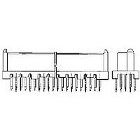
... Content This specification covers perform ance, tests and quality requirem ents for TE Connectivity (TE) Micro- Strip board to board right angle and vertical connector fam ily. These assem blies accom m odate a variety of printed circuit board thicknesses. Plug assem blies are loaded with .015 inch square m ale Micro-Strip contacts which m ate with receptacle assem blies loaded with fem ale Micro-Strip contacts ...

Page 2

Perform ance and Test Description Product is designed to m eet electrical, m echanical and environm ental perform ance requirem ents specified in Figure 1. All tests are perform bient environm ental conditions per Test Specification ...

Page 3

Test Description Mating force. Unm ating force. Durability. Therm al shock. Hum idity-tem perature cycling. Mixed flowing gas. Tem perature life. Shall meet visual requirements, show no physical damage and shall meet requirements of NOTE additional tests as specified in ...

Page 4

Loading Configuration Single (1 bus contact) 40% (2 bus contacts) 100% (5 bus contacts) 50% signal contacts pere, tem perature rise at 100% bus contact To determine acceptable current carrying capacity for percentage connector loading, use NOTE ...

Page 5

Product Qualification and Requalification Test Sequence Exam ination of product Term ination resistance, dry circuit Dielectric withstanding voltage Insulation resistance Tem perature rise vs current Vibration Physical shock Mating force Unm ating force Durability Therm al shock Hum idity-tem ...

Page 6

QUALITY ASSURANCE PROVISIONS 4.1. Qualification Testing A. Sam ple Selection Connector housings and contacts shall be prepared in accordance with applicable Instruction Sheets and shall be selected at random from current production. Test group 1 shall consist of 5 ...

Page 7

Resistance and Tem perature Measurem ent Points Rev A Figure 4 108-1272 ...

Page 8

Mounting and Clam ping Location for Vibration and Physical Shock Rev A Figure 5 108-1272 ...

Related keywords