583861-3 TE Connectivity, 583861-3 Datasheet
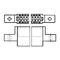
TW-LF CRP HSG 40 POS

583861-3

Manufacturer Part Number
583861-3
Description
TW-LF CRP HSG 40 POS
Manufacturer
TE Connectivity
Datasheets

Specifications of 583861-3

Rohs Compliant
YES
Product Type
Housing
Number Of Dual Positions
40
Mounting Ears
With
Centerline (mm [in])
2.54 [0.100]
Housing Material
Polyester GF
Housing Color
Black
Ul Flammability Rating
UL 94V-0
Rohs/elv Compliance
RoHS compliant, ELV compliant
Lead Free Solder Processes
Not relevant for lead free process
Rohs/elv Compliance History
Always was RoHS compliant
1.
1.1.
1.2.
2.
2.1.
3.
3.1.
3.2.
3.3.
©2011 Tyco Electronics Corporation,
a TE Connectivity Ltd. Company
All Rights Reserved
TE logo is a trademark.
SCOPE
Content
This specification covers the performance, tests and quality requirements for Crimp Snap Twin Leaf
Connector assemblies, used to provide a connection method between discrete wiring and printed circuit
boards. Contacts are crimp type, wrap in design. These multi-contact connectors have .100, .125 and
.156 inch centerline spacing between adjacent contacts.
Qualification
When tests are performed on the subject product line, the procedures specified in 109-Series Test
Specifications shall be used. All inspections shall be performed using the applicable inspection plan
and product drawing.
APPLICABLE DOCUMENTS
The following documents form a part of this specification to the extent specified herein. In the event of
conflict between the requirements of this specification and the product drawing, the product drawing
shall take precedence. In the event of conflict between the requirements of this specification and the
referenced documents, this specification shall take precedence.
TE Connectivity (TE) Documents
A.
B.
C.
D.
REQUIREMENTS
Design and Construction
Connectors shall be of the design, construction and physical dimensions specified on the applicable
product drawing.
Ratings
A.
B.
Performance and Test Description
Connectors shall be designed to meet the electrical, mechanical and environmental performance
requirements specified in Figure 1.
109-1:
109 Series:
114-:
501- :
Current: 5 amperes maximum per contact
Operating Temperature: -550 to 1050C
General Requirements for Test Specifications
Application Specification
Test Report
Series Type
Specification
Twin Leaf Crimp Snap Connector
| Indicates Change
*Trademark
Test Specifications as indicated in Figure 1.
Other products, logos, and company names might be trademarks of their respective owners.
For latest revision, visit out website at www.te.com/documents
For Regional Customer service, visit our website at www.te.com
108-9031
11 Mar 11 Rev D
1 of 8
LOC B

Related parts for 583861-3

583861-3 Summary of contents

Page 1

... Performance and Test Description Connectors shall be designed to meet the electrical, mechanical and environmental performance requirements specified in Figure 1. ©2011 Tyco Electronics Corporation, | Indicates Change a TE Connectivity Ltd. Company *Trademark All Rights Reserved TE logo is a trademark. For latest revision, visit out website at www.te.com/documents For Regional Customer service, visit our website at www ...

Page 2

Test Requirements and Procedures Summary Test Description Examination of Product Termination Resistance, Specified Current Termination Resistance, Dry Circuit Dielectric Withstanding Voltage Insulation Resistance Current Cycling Crimp Resistance Vibration Physical Shock Test Description Rev D Requirement Meets requirements of product ...

Page 3

Mating Force Contact Retention (Crimped Contacts) Contact Engaging Force Contact Separating Force Crimp Tensile Durability Thermal Shock Humidity, Steady State Rev D 12 ounces maximum per contact pair. Contacts shall not dislodge from normal locking position. 10 ounces maximum per ...

Page 4

Connector Qualification and Requalification Tests and Sequences Test or Examination Examination of Product Termination Resistance, Current Termination Resistance, Dry Circuit Dielectric Withstanding Voltage Insulation Resistance Crimp Resistance Current Cycling Vibration Physical Shock Connector Mating Force Contact Retention Contact Engaging ...

Page 5

C. Acceptance 1. Test results from development on pre-qualification samples will be used to determine upper and lower one-sided statistical tolerance limits for 99% reliability at 95% confidence, as follows. Let Xbar and s denote the sample average and standard ...

Page 6

Dimensions are in inches. NOTES 2. Unless otherwise specified, tolerance is +/-.005. 3. The test card shall extend 4.00 +/-.02 from the receptacle after insertion. 4. Number of contacts shall be the same as on the corresponding printed wiring ...

Page 7

Rev D Figure 5 Termination Resistance Test Circuit Figure 6 Crimp Resistance 108-9031 ...

Page 8

Tolerances: +/-.005 unless otherwise indicated. NOTES 2. Material: Tool steel, hardened to Rockwell C50-55. 3. Gage surface shall be clean of contaminants or lubricants. Rev D Gage A B Number 1 .0700 (a) 2 .0540 (a) Figure 7 Printed ...

Related keywords