AD872AJD Analog Devices Inc, AD872AJD Datasheet - Page 9
AD872AJD
Manufacturer Part Number
AD872AJD
Description
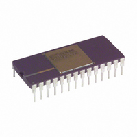
IC ADC 12BIT 10MSPS 28-CDIP
Manufacturer
Analog Devices Inc
Datasheet
1.AD872AJD.pdf
(20 pages)
Specifications of AD872AJD
Data Interface
Parallel
Rohs Status
RoHS non-compliant
Number Of Bits
12
Sampling Rate (per Second)
10M
Number Of Converters
7
Power Dissipation (max)
1.3W
Voltage Supply Source
Analog and Digital, Dual ±
Operating Temperature
0°C ~ 70°C
Mounting Type
Through Hole
Package / Case
28-CDIP (0.600", 15.24mm)
Resolution (bits)
12bit
Sampling Rate
10MSPS
Input Channel Type
Differential, Single Ended
Supply Voltage Range - Analog
± 4.75V To ± 5.25V
Supply Current
115mA
Lead Free Status / RoHS Status
Contains lead / RoHS non-compliant
Available stocks
Company
Part Number
Manufacturer
Quantity
Price

Part Number:
AD872AJD
Manufacturer:
ADI/亚德诺
Quantity:
20 000


THEORY OF OPERATION
The AD872A is implemented using a 4-stage pipelined multiple
flash architecture. A differential input track-and-hold amplifier
(THA) acquires the input and converts the input voltage into a
differential current. A 4-bit approximation of the input is made
by the first flash converter, and an accurate analog representa-
tion of this 4-bit guess is generated by a digital-to-analog con-
verter. This approximation is subtracted from the THA output
to produce a remainder, or residue. This residue is then sam-
pled and held by the second THA, and a 4-bit approximation is
generated and subtracted by the second stage. Once the second
THA goes into hold, the first stage goes back into track to
acquire a new input signal. The third stage provides a 3-bit ap-
proximation/subtraction operation, and produces the final resi-
due, which is passed to a final 4-bit flash converter. The 15
output bits from the 4 flash converters are accumulated in the
correction logic block, which adds the bits together using the
appropriate correction algorithm, to produce the 12-bit output
word. The digital output, together with overrange indicator, is
latched into an output buffer to drive the output pins.
The additional THA inserted in each stage of the AD872A
architecture allows pipelining of the conversion. In essence, the
converter is converting multiple inputs simultaneously, process-
ing them through the converter chain serially. This means that
while the converter is capable of capturing a new input sample
every clock cycle, it actually takes three clock cycles for the con-
version to be fully processed and appear at the output. This
“pipeline delay” is often referred to as latency, and is not a con-
cern in most applications, however there are some cases where it
may be a consideration. For example, some applications call for
the A/D converter to be placed in a high speed feedback loop,
where its input is servoed to provide a desired result at the digi-
tal output (e.g., offset calibration or zero restoration in video
applications). In these cases the three clock cycle delay through
the pipeline must be accounted for in the loop stability calcula-
tions. Also, because the converter is working on three conver-
sions simultaneously, major disruptions to the part (such as a
large glitch on the supplies or reference) may corrupt three data
samples. Finally, there will be a minimum clock rate below
which the THA droop corrupts the signal in the pipeline. In the
case of the AD872A, this minimum clock rate is 10 kHz.
The high impedance differential inputs of the AD872A allow a
variety of input configurations (see APPLYING THE AD872A),
The AD872A converts the voltage difference between the V
and V
(V
ential input can provide a performance boost: for example, for
an input coming from a coaxial cable, V
shield ground, allowing the AD872A to reject shield noise as
common mode. The high input impedance of the device mini-
mizes external driving requirements and allows the user to exter-
nally select the appropriate termination impedance for the
application.
The AD872A clock circuitry uses both edges of the clock in its
internal timing circuitry (see spec page for exact timing require-
ments). The AD872A samples the analog input on the rising
edge of the clock input. During the clock low time (between the
falling edge and rising edge of the clock) the input THA is in
track mode; during the clock high time it is in hold. System dis-
turbances just prior to the rising edge of the clock may cause the
part to acquire the wrong value, and should be minimized.
REV. A
INA
INB
or V
pins. For single-ended applications, one input pin
INB
) may be grounded, but even in this case the differ-
INB
can be tied to the
INA
–9–
While the part uses both clock edges for its timing, jitter is only
a significant issue for the rising edge of the clock (see CLOCK
INPUT section).
APPLYING THE AD872A ANALOG INPUTS
The AD872A features a high impedance differential input that
can readily operate on either single-ended or differential input
signals. Table I summarizes the nominal input voltage span for
both single-ended and differential modes, assuming a 2.5 V
reference input.
Single-Ended
Differential
Figure 10 shows an approximate model for the analog input cir-
cuit. As this model indicates, when the input exceeds 1.6 V
(with respect to AGND), the input device may saturate, causing
the input impedance to drop substantially and significantly re-
ducing the performance of the part. Input compliance in the
negative direction is somewhat larger, showing virtually no deg-
radation in performance for inputs as low as –1.9 V.
Figure 11 illustrates the effect of varying the common-mode
voltage of a –0.5 dB input signal on total harmonic distortion.
Figure 11. AD872A Total Harmonic Distortion vs. CM Input
Voltage, f
Figure 10. AD872A Equivalent Analog Input Circuit
–100
–10
–20
–30
–40
–50
–60
–70
–80
–90
0
–1
IN
= 1 MHz, FS = 10 MSPS
–0.8
V
INA
V
+1 V
+0.5 V
–0.5 V
–1 V
Table I. Input Voltage Span
–0.6 –0.4
INA
OR V
1V
INB
CM INPUT VOLTAGE – V
–0.2
V
GND
GND
–0.5 V
+0.5 V
INB
–1.9V
1.75mA
5pF
0
–5V
+5V
V
+1 V (Positive Full Scale)
–1 V (Negative Full Scale)
+1 V (Positive Full Scale)
–1 V (Negative Full Scale)
0.2
INA
1.75mA
0.4
AD872A
–V
INB
0.6
+1.6V
AD872A
0.8
1.0
Related parts for AD872AJD
Image
Part Number
Description
Manufacturer
Datasheet
Request
R

Part Number:
Description:
±1.7g Dual-Axis IMEMS Accelerometer Evaluation Board
Manufacturer:
Analog Devices Inc
Datasheet:

Part Number:
Description:
Inertial Sensor Evaluation System
Manufacturer:
Analog Devices Inc
Datasheet:
Part Number:
Description:
Manufacturer:
Analog Devices Inc
Datasheet:
Part Number:
Description:
Manufacturer:
Analog Devices Inc
Datasheet:
Part Number:
Description:
Manufacturer:
Analog Devices Inc
Datasheet:
Part Number:
Description:
Manufacturer:
Analog Devices Inc
Datasheet:
Part Number:
Description:
Manufacturer:
Analog Devices Inc
Datasheet:
Part Number:
Description:
Manufacturer:
Analog Devices Inc
Datasheet:
Part Number:
Description:
Manufacturer:
Analog Devices Inc
Datasheet:
Part Number:
Description:
Manufacturer:
Analog Devices Inc
Datasheet:
Part Number:
Description:
Manufacturer:
Analog Devices Inc
Datasheet:
Part Number:
Description:
Manufacturer:
Analog Devices Inc
Datasheet:
Part Number:
Description:
Manufacturer:
Analog Devices Inc
Datasheet: