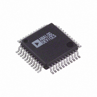
AD9260AS Analog Devices Inc, AD9260AS Datasheet - Page 32

AD9260AS
Manufacturer Part Number
AD9260AS
Description
IC ADC CMOS 16BIT OVRSAMP 44MQFP
Manufacturer
Analog Devices Inc
Datasheet
1.AD9260ASZRL.pdf
(44 pages)
Specifications of AD9260AS
Rohs Status
RoHS non-compliant
Number Of Bits
16
Sampling Rate (per Second)
20M
Data Interface
Parallel
Number Of Converters
1
Power Dissipation (max)
585mW
Voltage Supply Source
Analog and Digital
Operating Temperature
-40°C ~ 85°C
Mounting Type
Surface Mount
Package / Case
44-MQFP, 44-PQFP
Available stocks
Company
Part Number
Manufacturer
Quantity
Price
Company:
Part Number:
AD9260ASZ
Manufacturer:
ADI
Quantity:
100
Company:
Part Number:
AD9260ASZ
Manufacturer:
Analog Devices Inc
Quantity:
10 000
Part Number:
AD9260ASZ
Manufacturer:
ADI/亚德诺
Quantity:
20 000
Company:
Part Number:
AD9260ASZRL
Manufacturer:
Analog Devices Inc
Quantity:
10 000
AD9260
Table 15. Recommended Mode Pin Ranges
and Configurations
Mode Pin Range
0 V–0.5 V
0.5 V–1.5 V
1.5 V–3.0 V
3.0 V–5.0 V
BIAS PIN OPERATION
The Bias Select Pin (BIAS) gives the user, who is able to operate
the AD9260 at a slower clock rate, the added flexibility of
running the device in a lower, power consumption mode when
it is clocked at less than 20 MHz.
This is accomplished by scaling the bias current of the AD9260
as illustrated in Figure 69. The bias amplifier drives a source
follower and forces 1 V across R
This effectively adjusts the bias current in the modulator
amplifiers and FLASH preamplifiers. When a large value of R
is used, a smaller bias current is available to the internal
amplifier circuitry. As a result these amplifiers need more time
to settle, thus dictating the use of a slower clock as the power
is reduced. Refer to the characterization curves shown in Figure
47 to Figure 54 revealing the performance tradeoffs.
The scaling is accomplished by properly attaching an external
resistor to the BIAS pin of the AD9260 as shown in Table 17.
R
inversely with clock rate. Because BIAS is an external pin,
minimization of capacitance to this pin is recommended in
order to prevent instability of the bias pin amplifier.
EXT
is normally 2 kΩ for a clock speed of 20 MHz and scales
Typical Mode Pin
GND
VREF/2
CML
AVDD
EXT
, which sets the bias current.
Decimation Mode
8×
2×
4×
1×
Rev. C | Page 32 of 44
EXT
MODE PIN
1V
4R
3R
2R
AVDD
R
Figure 68. Simplified Mode Pin Circuitry
AVSS
Figure 69. Simplified Bias Pin Circuitry
BIAS CURRENT
REXT
LATCH
CLOCK
BIAS PIN
ENCODED MODE


