3613C330K TE Connectivity, 3613C330K Datasheet - Page 2
3613C330K
Manufacturer Part Number
3613C330K
Description
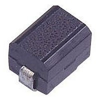
CHIP INDUCTOR, 33UH 160MA 10% 11MHZ
Manufacturer
TE Connectivity
Series
3613r
Datasheet
1.3613C101K.pdf
(2 pages)
Specifications of 3613C330K
Inductance
33µH
Inductance Tolerance
± 10%
Dc Resistance Max
4ohm
Dc Current Rating
160mA
Q Factor
50
Self Resonant Frequency
11MHz
Core Material
Ferrite
Inductor Case Style
1812
Rohs Compliant
Yes
Product Type
Inductor
Inductor Type
Molded Wirewound
Element
Wirewound
Inductance (µh)
33
Dc Resistance (?)
4
Current, Maximum (ma)
160
Quality Factor
50
Package Type
Taped and Reeled
Shielded
No
Tolerance (%)
10
Lead Type
Surface Mount Terminals
Packaging Style
1812
Package, Component Size
4.5 x 3.2
Mount Style
Surface Mount
Rohs/elv Compliance
RoHS compliant, ELV compliant
Lead Free Solder Processes
Reflow solder capable to 245°C, Reflow solder capable to 260°C
Rohs/elv Compliance History
Converted to comply with RoHS directive
Application
Standard
Available stocks
Company
Part Number
Manufacturer
Quantity
Price

Part Number:
3613C330K
Manufacturer:
TETYCO
Quantity:
20 000


Test Methods
Literature No. 1773143
Issued: 07-05
Item
DC Superposition
Characteristics
Temperature
Rise
Temperature
Rise
Overcurrent
Test
Insulation
Resistance
Tensile
Strength Test
Stress Test
Drop Test
Vibration Test
Humidity Resistance
Load Test
Low Temperature
Resistance Test
Temperature
Cycle Test
High Temperature
Resistance Load Test
Dimensions are shown for
reference purposes only.
Test Notes
Dimensions
Standard
∆L/L Within -10%
Within 20°C
∆L/L Within ± 5%
No smoke and no fire
Not less than 1000 M
No separation from substrate
No breakage
No pronounced abnormality in
appearance
∆L/L Within ± 10%
Q Not less than 30
∆L/L Within ± 10%
Q Not less than 30
∆L/L Within ± 10%
Q Not less than 30
∆L/L Within ± 10%
Q Not less than 30
∆L/L Within ± 10%
Q Not less than 30
Moulded Chip Inductor 18:12
Type 3613C Series
How to Order
The measuring method for the test data given overpage are as follows:
Inductance: Direct reading from Q-meter (equivalent to YHP 4342A, jig used)
Q: Direct reading from Q-meter (equivalent to YHP 4342A, jig used)
Self resonant frequency: Grid Dipo Meter (equivalent to Measurement M159)
DC resistance: Wheatstone bridge (equivalent to YEW 2755)
Unless otherwise specified, the temperature is 20°C ± 5°C and the humidity is 65% ± 20%
Common Part
3613C - 18:12
Dimensions are in millimetres
unless otherwise specified.
3613C
Inductor
Test Method
When the allowable current was applied, the inductance was measured
with a YHP 4262A and compared with the initial value.
When the allowable current was applied, the amount of temperature rise
was measured by the change in resistance.
Measurements were taken in a temperature range of -25°C to 85°C and
the value at +20°C was used as the standard value.
Twice the allowable current was applied for a period of five minutes.
0.3mm diameter copper wires were wound around the coils three times and
measurements were taken after 250VDC was applied between the wire and the
terminals for a period of 1 minute.
After the inductors were soldered to substrates, a force of 1.0kg was applied in both
the x and y directions for a period of 5 seconds.
After the inductors were mounted on substrates, 1-mins. 10-55-10 cycle per seconds
sweeps 1.5mm stroke vibrations were applied for 2 hrs. each in the X, Y and Z directions.
The inductors were dropped 10 times from a height of 1.0 metre onto a concrete floor.
After the inductors were mounted on substrates, 1-mins. 10-55-10 cycle per seconds
sweeps 1.5mm stroke vibrations were applied for 2 hours each in the X, Y and Z
directions
Measurements were taken after the allowable current was applied while the inductors
were stored at 60°C ± 2°C in 90 to 95% RH for a period of 500 hours.
Measurements were taken after the inductors were stored at -40°C ± 2°C for period
1000 hours
Measurements were taken after the inductors were stored for 30 minutes, during which
they were subjected to 20 temperature cycles of between -25°C and +85°C.
Measurements were taken after the allowable was applied while the inductors were stored
at 85°C for a period of 1000 hours.
Inductance
Value Code
(see table)
Specifications subject to
change.
1R5
Tolerance
K - ±10%
M - 20%
J - ±5%
www.tycoelectronics.com
passives.tycoelectronics.com
K
Related parts for 3613C330K
Image
Part Number
Description
Manufacturer
Datasheet
Request
R

Part Number:
Description:
3613C 10UH 10%
Manufacturer:
TE Connectivity
Datasheet:
Part Number:
Description:
3613C 1.0UH 10%
Manufacturer:
TE Connectivity
Datasheet:
Part Number:
Description:
3613C 3.3UH 10%
Manufacturer:
TE Connectivity
Datasheet:

Part Number:
Description:
3613C 150UH 10%
Manufacturer:
TE Connectivity
Datasheet:

Part Number:
Description:
3613C 330UH 10%
Manufacturer:
TE Connectivity
Datasheet:
Part Number:
Description:
3613C 8.2UH 10%
Manufacturer:
TE Connectivity
Datasheet:
Part Number:
Description:
INDUCTOR 47UH 140MA 1812
Manufacturer:
TE Connectivity
Datasheet:
Part Number:
Description:
INDUCTOR 100UH 110MA 1812
Manufacturer:
TE Connectivity
Datasheet:
Part Number:
Description:
INDUCTOR 680NH 500MA 1812
Manufacturer:
TE Connectivity
Datasheet:


Part Number:
Description:
Manufacturer:
TE Connectivity
Datasheet:


Part Number:
Description:
Manufacturer:
TE Connectivity
Datasheet:

Part Number:
Description:
Manufacturer:
TE Connectivity
Datasheet: