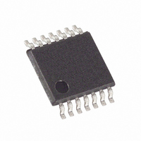
MAX5488EUD+ Maxim Integrated Products, MAX5488EUD+ Datasheet

MAX5488EUD+
Specifications of MAX5488EUD+
Related parts for MAX5488EUD+
MAX5488EUD+ Summary of contents
Page 1
... DECODER LATCH MAX5487 MAX5488 MAX5489 ________________________________________________________________ Maxim Integrated Products For pricing, delivery, and ordering information, please contact Maxim Direct at 1-888-629-4642, or visit Maxim’s website at www.maxim-ic.com. o Wiper Position Stored in Nonvolatile Memory (EEPROM) and Recalled Upon Power-Up or Recalled by an Interface Command o 3mm x 3mm x 0.8mm, 16-Pin TQFN or 14-Pin TSSOP Packages o ± ...
Page 2
Dual, 256-Tap, Nonvolatile, SPI-Interface, Linear-Taper Digital Potentiometers ABSOLUTE MAXIMUM RATINGS V to GND ...........................................................-0.3V to +6.0V DD All Other Pins to GND......................-0.3V to the lower of (V Maximum Continuous Current into H_, W_, and L_ MAX5487......................................................................±5.0mA MAX5488......................................................................±1.3mA MAX5489......................................................................±0.6mA Stresses beyond ...
Page 3
Dual, 256-Tap, Nonvolatile, SPI-Interface, Linear-Taper Digital Potentiometers DC ELECTRICAL CHARACTERISTICS (continued +2.7V to +5.25V +25°C, unless otherwise noted.) (Note 1) A PARAMETER SYMBOL DIGITAL INPUTS Input High ...
Page 4
Dual, 256-Tap, Nonvolatile, SPI-Interface, Linear-Taper Digital Potentiometers DC ELECTRICAL CHARACTERISTICS (continued +2.7V to +5.25V +25°C, unless otherwise noted.) (Note 1) A PARAMETER POWER SUPPLIES Power-Supply Voltage Supply ...
Page 5
Dual, 256-Tap, Nonvolatile, SPI-Interface, Linear-Taper Digital Potentiometers (V = +5.0V +25°C, unless otherwise noted SUPPLY CURRENT vs. TEMPERATURE MAX5487-89 toc01 0 0.5 0.4 0.3 0.2 0 -40 ...
Page 6
Dual, 256-Tap, Nonvolatile, SPI-Interface, Linear-Taper Digital Potentiometers (V = +5.0V +25°C, unless otherwise noted MIDSCALE FREQUENCY RESPONSE (MAX5488 10pF -5 W_ -10 - 50pF W_ -20 -25 -30 -35 -40 -45 ...
Page 7
Dual, 256-Tap, Nonvolatile, SPI-Interface, Linear-Taper Digital Potentiometers (V = +5.0V +25°C, unless otherwise noted VARIABLE-RESISTOR DNL vs. TAP POSITION (MAX5489) 0.20 0.15 0.10 0.05 0 -0.05 -0.10 -0.15 -0. 128 160 192 ...
Page 8
Dual, 256-Tap, Nonvolatile, SPI-Interface, Linear-Taper Digital Potentiometers PIN NAME TQFN TSSOP Power Supply. Bypass SCLK Serial-Interface Clock Input 3 12 DIN Serial-Interface Data Input Active-Low Chip-Select Digital Input 5, 6, ...
Page 9
Dual, 256-Tap, Nonvolatile, SPI-Interface, Linear-Taper Digital Potentiometers Table 1. Register Map 1 CLOCK EDGE — Write Wiper Register A 0 Write Wiper Register B 0 Write NV Register A 0 Write NV Register B 0 Copy Wiper Register A to ...
Page 10
Dual, 256-Tap, Nonvolatile, SPI-Interface, Linear-Taper Digital Potentiometers A) 16-BIT COMMAND/DATA WORD CS SCLK DIN 8-BIT COMMAND WORD CS SCLK DIN Figure 3. Digital-Interface Format or both simultaneously, depending ...
Page 11
Dual, 256-Tap, Nonvolatile, SPI-Interface, Linear-Taper Digital Potentiometers MAX5487 MAX5488 MAX5489 MAX480 L_ Figure 4. Positive LCD-Bias Control Using a Voltage-Divider 5V H_ MAX480 MAX5487 MAX5488 W_ MAX5489 L_ Figure 5. Positive LCD-Bias Control Using a Variable Resistor ...
Page 12
... HB 1/2 MAX5487/MAX5488/MAX5489 Figure 8. Offset Voltage and Gain Adjustment PART TEMP RANGE MAX5488ETE+ -40°C to +85°C MAX5488EUD+ -40°C to +85°C MAX5489ETE+ -40°C to +85°C MAX5489EUD+ -40°C to +85°C MAX5489ETE/V+ -40°C to +85° Exposed pad. + Denotes a lead(Pb)-free/RoHS-compliant package. /V denotes an automotive qualified part. ...
Page 13
... Maxim cannot assume responsibility for use of any circuitry other than circuitry entirely embodied in a Maxim product. No circuit patent licenses are implied. Maxim reserves the right to change the circuitry and specifications without notice at any time. Maxim Integrated Products, 120 San Gabriel Drive, Sunnyvale, CA 94086 408-737-7600 ____________________ 13 © 2010 Maxim Integrated Products DESCRIPTION Maxim is a registered trademark of Maxim Integrated Products, Inc ...


