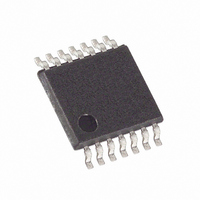
MAX5489EUD+ Maxim Integrated Products, MAX5489EUD+ Datasheet - Page 9

MAX5489EUD+
Manufacturer Part Number
MAX5489EUD+
Description
IC DGTL POT DUAL 256-TAP 14TSSOP
Manufacturer
Maxim Integrated Products
Datasheet
1.MAX5488EUD.pdf
(13 pages)
Specifications of MAX5489EUD+
Taps
256
Resistance (ohms)
100K
Number Of Circuits
2
Temperature Coefficient
35 ppm/°C Typical
Memory Type
Non-Volatile
Interface
SPI, 3-Wire Serial
Voltage - Supply
2.7 V ~ 5.25 V
Operating Temperature
-40°C ~ 85°C
Mounting Type
Surface Mount
Package / Case
14-TSSOP
Resistance In Ohms
100K
Number Of Pots
Dual
Taps Per Pot
256
Resistance
100 KOhms
Wiper Memory
Non Volatile
Digital Interface
Serial (3-Wire, SPI)
Operating Supply Voltage
2.7 V to 5.25 V
Supply Current
1 uA
Maximum Operating Temperature
+ 85 C
Minimum Operating Temperature
- 40 C
Description/function
Dual, 256 Tap, Nonvolatile, SPI, 100k Digital Potentiometer
Mounting Style
SMD/SMT
Supply Voltage (max)
5.25 V
Supply Voltage (min)
2.7 V
Tolerance
25 %
Lead Free Status / RoHS Status
Lead free / RoHS Compliant
Table 1. Register Map
Figure 2. Timing Diagram
Data written to the write-wiper registers (C1, C0 = 00)
controls the wiper positions. The 8 data bits (D7 to D0)
indicate the position of the wiper. For example, if DIN =
0000 0000, the wiper moves to the position closest to
L_. If DIN = 1111 1111, the wiper moves closest to H_.
This command writes data to the volatile RAM, leaving the
NV registers unchanged. When the device powers up,
the data stored in the NV registers transfers to the volatile
wiper register, moving the wiper to the stored position.
Write Wiper Register A
Write Wiper Register B
Write NV Register A
Write NV Register B
Copy Wiper Register A to NV
Register A
Copy Wiper Register B to NV
Register B
Copy Both Wiper Registers to
NV Registers
Copy NV Register A to Wiper
Register A
Copy NV Register B to Wiper
Register B
Copy Both NV Registers to
Wiper Registers
CLOCK EDGE
SCLK
DIN
CS
Dual, 256-Tap, Nonvolatile, SPI-Interface,
Write-Wiper Register (Command 00)
_______________________________________________________________________________________
t
CSO
t
CSS
Linear-Taper Digital Potentiometers
—
t
1
0
0
0
0
0
0
0
0
0
0
DS
—
2
0
0
0
0
0
0
0
0
0
0
C1
3
0
0
0
0
1
1
1
1
1
1
t
CL
C0
4
0
0
1
1
0
0
0
1
1
1
t
DH
t
CH
—
5
0
0
0
0
0
0
0
0
0
0
—
6
0
0
0
0
0
0
0
0
0
0
This command (C1, C0 = 01) stores the position of the
wipers to the NV registers for use at power-up.
Alternatively, the “copy wiper register to NV register”
command can be used to store the position of the
wipers to the NV registers. Writing to the NV registers
does not affect the position of the wipers.
This command (C1, C0 = 10) stores the current position
of the wiper to the NV register, for use at power-up.
This command may affect one potentiometer at a time,
Copy Wiper Register to NV Register (Command 10)
A1
7
0
1
0
1
0
1
1
0
1
1
A0
8
1
0
1
0
1
0
1
1
0
1
t
CP
D7
D7
D7
D7
D7
—
—
—
—
—
—
9
D6
D6
D6
D6
D6
10
—
—
—
—
—
—
Write-NV Register (Command 01)
t
D5
D5
D5
D5
D5
11
CSH
—
—
—
—
—
—
D4
D4
D4
D4
D4
12
—
—
—
—
—
—
t
CSW
D3
D3
D3
D3
D3
13
—
—
—
—
—
—
t
CS1
D2
D2
D2
D2
D2
14
—
—
—
—
—
—
D1
D1
D1
D1
D1
15
—
—
—
—
—
—
D0
D0
D0
D0
D0
16
—
—
—
—
—
—
9


