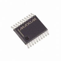
DS3930E+ Maxim Integrated Products, DS3930E+ Datasheet - Page 11

DS3930E+
Manufacturer Part Number
DS3930E+
Description
IC POT NV HEX I/O MEM 20-TSSOP
Manufacturer
Maxim Integrated Products
Datasheet
1.DS3930E.pdf
(12 pages)
Specifications of DS3930E+
Taps
256
Resistance (ohms)
16.5K
Number Of Circuits
6
Temperature Coefficient
250 ppm/°C Typical
Memory Type
Non-Volatile
Interface
I²C, 2-Wire Serial
Voltage - Supply
2.7 V ~ 5.5 V
Operating Temperature
-40°C ~ 85°C
Mounting Type
Surface Mount
Package / Case
20-TSSOP
Resistance In Ohms
16.5K
Lead Free Status / RoHS Status
Lead free / RoHS Compliant
Figure 5. 2-Wire AC Characteristics
Figure 6. Example 2-Wire Transactions
To achieve the best results when using the DS3930,
decouple the power supply with a 0.1µF high-quality,
ceramic, surface-mount capacitor. Surface-mount com-
SDA
SCL
*THE ADDRESS DETERMINED BY A0, A1, AND A2 MUST
TYPICAL 2-WIRE WRITE TRANSACTION
MATCH THE ADDRESS SET BY THE ADDRESS PINS.
EXAMPLE 2-WIRE TRANSACTIONS (WHEN A0, A1, AND A2 ARE ZERO)
START
A) SINGLE-BYTE WRITE
-WRITE TO POT 0 REGISTER
C) SINGLE-BYTE WRITE
-SET I/O
B) SINGLE-BYTE READ
-READ FROM POT 0 REGISTER
D) MULTIPLE BYTE WRITE
-2 BYTE WRITE TO EEPROM
E) MULTIPLE BYTE READ
-2 BYTE READ FROM EEPROM
STOP
MSB
DEVICE IDENTIFIER
1
0
t
PIN TO A "1"
BUF
Applications Information
0
START
1
0
Power Supply Decoupling
A2*
t
ADDRESS
HD:STA
DEVICE
t
START
LOW
START
START
START
START
A1*
Hex Nonvolatile Potentiometer with
A0*
1 0 1 0 0 0 0 0
1 0 1 0 0 0 0 0
1 0 1 0 0 0 0 0
1 0 1 0 0 0 0 0
1 0 1 0 0 0 0 0
READ/
WRITE
LSB
R/W
A0h
A0h
A0h
A0h
A0h
SLAVE
ACK
____________________________________________________________________
t
R
t
HD:DAT
SLAVE
SLAVE
SLAVE
SLAVE
SLAVE
ACK
ACK
ACK
ACK
ACK
MSB
b7
0 0 0 0 0 0 0 0
0 0 0 0 0 0 0 0
1 1 1 1 0 0 0 0
1 1 1 1 0 0 0 0
1 1 1 1 0 1 1 0
b6
t
F
F0h
F0h
F6h
00h
00h
t
REGISTER ADDRESS
HIGH
b5
b4
SLAVE
SLAVE
SLAVE
SLAVE
SLAVE
ACK
ACK
ACK
ACK
ACK
b3
t
SU:DAT
POT SETTING
X X X 0 X X X 1
b2
REPEATED
REPEATED
START
START
DATA
DATA
DATA
ponents minimize lead inductance, which improves
performance, and ceramic capacitors tend to have
adequate high-frequency response for decoupling
applications. The capacitor should be placed as close
as possible to the V
b1
LSB
b0
REPEATED
1 0 1 0 0 0 0 1
1 0 1 0 0 0 0 1
START
SLAVE
SLAVE
SLAVE
ACK
ACK
ACK
SLAVE
SLAVE
A1h
ACK
ACK
A1h
MSB
STOP
STOP
t
b7
SU:STA
SLAVE
SLAVE
DATA
ACK
ACK
t
HD:STA
b6
POT SETTING
I/O and Memory
b5
DATA
DATA
SLAVE
CC
ACK
b4
DATA
and GND pins.
b3
STOP
MASTER
MASTER
NACK
ACK
b2
b1
STOP
LSB
b0
DATA
t
SP
SLAVE
ACK
MASTER
NACK
STOP
t
SU:STO
STOP
11


