MCP4017T-503E/LT Microchip Technology, MCP4017T-503E/LT Datasheet - Page 42

MCP4017T-503E/LT
Manufacturer Part Number
MCP4017T-503E/LT
Description
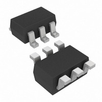
IC DGTL POT 50K 128TAPS SC70-6
Manufacturer
Microchip Technology
Datasheet
1.MCP4018T-502ELT.pdf
(66 pages)
Specifications of MCP4017T-503E/LT
Package / Case
SC-70-6, SC-88, SOT-363
Temperature Coefficient
150 ppm/°C Typical
Taps
128
Resistance (ohms)
50K
Number Of Circuits
1
Memory Type
Volatile
Interface
I²C, 2-Wire Serial
Voltage - Supply
1.8 V ~ 5.5 V
Operating Temperature
-40°C ~ 125°C
Mounting Type
Surface Mount
Resistance In Ohms
50K
Number Of Pots
Single
Taps Per Pot
128
Resistance
50 KOhms
Wiper Memory
Volatile
Buffered Wiper
Buffered
Digital Interface
Serial (2-Wire, I2C)
Operating Supply Voltage
2.5 V or 3.3 V or 5 V
Supply Current
0.045 mA (Typ)
Maximum Operating Temperature
+ 125 C
Minimum Operating Temperature
- 40 C
Description/function
7 Bit Single I2C Digital Rheostat
Mounting Style
SMD/SMT
Supply Voltage (max)
5.5 V
Supply Voltage (min)
1.8 V
Tolerance
20 %
End To End Resistance
50kohm
Track Taper
Linear
No. Of Steps
128
Resistance Tolerance
± 20%
Supply Voltage Range
1.8V To 5.5V
Control Interface
I2C
No. Of Pots
Single
Rohs Compliant
No
Lead Free Status / RoHS Status
Lead free / RoHS Compliant
Lead Free Status / RoHS Status
Lead free / RoHS Compliant, Lead free / RoHS Compliant
Other names
MCP4017T-503E/LTTR
Available stocks
Company
Part Number
Manufacturer
Quantity
Price
Company:
Part Number:
MCP4017T-503E/LT
Manufacturer:
AMS
Quantity:
2 300
Part Number:
MCP4017T-503E/LT
Manufacturer:
MICROCHIP/微芯
Quantity:
20 000
MCP4017/18/19
Step resistance (R
setting to the next. This value will be dependent on the
R
the calculation for the step resistance while
shows the typical step resistances for each device.
EQUATION 6-1:
Equation 6-2
determine the resistance between the wiper and
terminal B.
EQUATION 6-2:
The digital potentiometer is available in four nominal
resistances (R
defined as the resistance between terminal A and
terminal B. The four nominal resistances are 5 kΩ,
10 kΩ, 50 kΩ, and 100 kΩ.
The total resistance of the device has minimal variation
due to operating voltage (see
Figure
TABLE 6-2:
DS22147A-page 42
MCP4017/18/19-502E
MCP4017/18/19-103E
MCP4017/18/19-503E
MCP4017/18/19-104E
AB
value that has been selected.
Part Number
2-47, or
illustrates the calculation used to
AB
Figure
N = 0 to 127 (decimal)
) where the nominal resistance is
R
STEP RESISTANCES
R
WB
S
S
) is the resistance from one tap
=
2-65).
R
R
=
S
WB
R
---------
127
Case
Min.
Typical 5000
Max.
Min.
Typical 10000
Max.
Min.
Typical 50000
Max.
Min.
Typical 100000
Max.
R
------------- -
AB
CALCULATION
127
AB
CALCULATION
N
Figure
+
Resistance (Ω)
R
40000
60000
80000
120000
4000
6000
8000
12000
Equation 6-1
W
(R
Total
2-11,
AB
)
Figure
Step (R
Table 6-2
314.961
393.701
472.441
629.921
787.402
944.882
31.496
39.370
47.244
62.992
78.740
94.488
shows
2-29,
S
)
A POR/BOR event will load the Volatile Wiper register
value with the default value.
default values offered.
TABLE 6-3:
Resistance
-502
-103
-503
-104
Note 1: Custom POR/BOR Wiper Setting options
Code
are available, contact the local Microchip
Sales Office for additional information.
Custom options have minimum volume
requirements.
R
100.0 kΩ
10.0 kΩ
50.0 kΩ
Typical
AB
5.0 kΩ
DEFAULT FACTORY
SETTINGS SELECTION
Value
© 2009 Microchip Technology Inc.
Mid-scale
Mid-scale
Mid-scale
Mid-scale
Default POR Wiper
Setting
Table 6-3
shows the
Code
3Fh
3Fh
3Fh
3Fh
(1)


