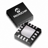
MCP4241T-104E/ML Microchip Technology, MCP4241T-104E/ML Datasheet - Page 47

MCP4241T-104E/ML
Manufacturer Part Number
MCP4241T-104E/ML
Description
IC DGTL POT 100K 2CH 16QFN
Manufacturer
Microchip Technology
Specifications of MCP4241T-104E/ML
Package / Case
16-QFN
Taps
129
Resistance (ohms)
100K
Number Of Circuits
2
Temperature Coefficient
150 ppm/°C Typical
Memory Type
Non-Volatile
Interface
SPI Serial
Voltage - Supply
2.7 V ~ 5.5 V
Operating Temperature
-40°C ~ 125°C
Mounting Type
Surface Mount
Resistance In Ohms
100K
Number Of Pots
Dual
Taps Per Pot
128
Resistance
100 KOhms
Wiper Memory
Non Volatile
Digital Interface
Serial (4-Wire, SPI)
Operating Supply Voltage
2.5 V, 3.3 V, 5 V
Supply Current
550 uA
Maximum Operating Temperature
+ 125 C
Minimum Operating Temperature
- 40 C
Mounting Style
SMD/SMT
Supply Voltage (max)
5.5 V
Supply Voltage (min)
1.8 V
Lead Free Status / RoHS Status
Lead free / RoHS Compliant
Other names
MCP4241T-104-E/ML
MCP4241T-104-E/MLTR
MCP4241T-104-E/MLTR
MCP4241T-104E/MLTR
MCP4241T-104-E/MLTR
MCP4241T-104-E/MLTR
MCP4241T-104E/MLTR
7.2
Only the Read Command and the Write Command use
the Data Byte, see
concatenate the 8-bits of the Data Byte with the one
data bit (D8) contained in the Command Byte to form
9-bits of data (D8:D0). The Command Byte format
supports up to 9-bits of data so that the 8-bit resistor
network can be set to Full Scale (100h or greater). This
allows wiper connections to Terminal A and to
Terminal B.
The D9 bit is currently unused, and corresponds to the
position on the SDO data of the CMDERR bit.
7.3
The CMDERR bit indicates if the four address bits
received (AD3:AD0) and the two command bits
received (C1:C0) are a valid combination (see
Table
is valid and low if the combination is invalid.
The command error bit will also be low if a write to a
Non-Volatile Address has been specified and another
SPI command occurs before the CS pin is driven
inactive (V
SPI commands that do not have a multiple of 8 clocks
are ignored.
Once an error condition has occurred, any following
commands are ignored. All following SDO bits will be
low until the CMDERR condition is cleared by forcing
the CS pin to the inactive state (V
© 2008 Microchip Technology Inc.
4-1). The CMDERR bit is high if the combination
Data Byte
Error Condition
IH
).
Figure
7-1. These commands
IH
).
MCP414X/416X/424X/426X
7.3.1
All SPI transmissions must have the correct number of
SCK pulses to be executed. The command is not
executed until the complete number of clocks have
been received. Some commands also require the CS
pin to be forced inactive (V
the inactive state (V
Partial commands are not executed.
SPI is more susceptible to noise than other bus
protocols. The most likely case is that this noise
corrupts the value of the data being clocked into the
MCP4XXX or the SCK pin is injected with extra clock
pulses. This may cause data to be corrupted in the
device, or a command error to occur, since the address
and command bits were not a valid combination. The
extra SCK pulse will also cause the SPI data (SDI) and
clock (SCK) to be out of sync. Forcing the CS pin to the
inactive state (V
interface will ignore activity on the SDI and SCK pins
until the CS pin transition to the active state is detected
(V
IH
Note 1: When data is not being received by the
to V
IL
2: It is also recommended that long continu-
or V
ABORTING A TRANSMISSION
MCP4XXX, It is recommended that the
CS pin be forced to the inactive level (V
ous command strings should be broken
down into single commands or shorter
continuous
reduces the probability of noise on the
SCK pin corrupting the desired SPI
commands.
IH
IH
to V
) resets the serial interface. The SPI
IH
IHH
) the serial interface is reset.
).
command
IH
). If the CS pin is forced to
DS22059B-page 47
strings.
This
IL
)


