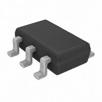
MAX5434MEZT+T Maxim Integrated Products, MAX5434MEZT+T Datasheet - Page 12

MAX5434MEZT+T
Manufacturer Part Number
MAX5434MEZT+T
Description
IC POT DGTL 32TAP NV TSOT23-6
Manufacturer
Maxim Integrated Products
Datasheet
1.MAX5434LEZTT.pdf
(19 pages)
Specifications of MAX5434MEZT+T
Taps
32
Resistance (ohms)
50K
Number Of Circuits
1
Temperature Coefficient
35 ppm/°C Typical
Memory Type
Non-Volatile
Interface
I²C, 2-Wire Serial
Voltage - Supply
2.7 V ~ 5.25 V
Operating Temperature
-40°C ~ 85°C
Mounting Type
Surface Mount
Package / Case
TSOT-23-6, TSOT-6
Resistance In Ohms
50K
Lead Free Status / RoHS Status
Lead free / RoHS Compliant
32-Tap, Nonvolatile, I
Potentiometers
Figure 9. Positive LCD Bias Control Using a Voltage-Divider
Use the MAX5432–MAX5435 in applications requiring
digitally controlled adjustable resistance, such as LCD
contrast control (where voltage biasing adjusts the dis-
play contrast), or for programmable filters with
adjustable gain and/or cutoff frequency.
Figures 9 and 10 show an application where the volt-
age-divider or variable resistor is used to make an
adjustable, positive LCD bias voltage. The op-amp pro-
vides buffering and gain to the resistor-divider network
made by the potentiometer (Figure 9) or to a fixed
resistor and a variable resistor (Figure 10).
Figure 11 shows the configuration for a 1st-order pro-
grammable filter. The gain of the filter is adjusted by
12
Figure 11. Programmable Filter
______________________________________________________________________________________
V
MAX5432
MAX5433
IN
H
MAX5432–
MAX5435
Applications Information
R3
W
5V
H
L
Positive LCD Bias Control
L
W
R2
C
H
L
Programmable Filter
W
30V
R1
V
V
OUT
OUT
2
C, Linear, Digital
R2, and the cutoff frequency is adjusted by R3. Use the
following equations to calculate the gain (G) and the
3dB cutoff frequency (f
Figure 12 shows the MAX5432/MAX5433 used as the
feedback resistors in an adjustable voltage reference
application. Independently adjust the output voltages of
the MAX6160 from 1.23V to (V
the wiper position of the MAX5432/MAX5433.
Figure 10. Positive LCD Bias Control Using a Variable Resistor
Figure 12. Adjustable Voltage Reference
MAX5432–
MAX5435
V
V
0
0
= 1.23V
= 1.23V
Adjustable Voltage Reference
MAX6160
H
L
5V
GND
+5V
V
100kΩ
R2(kΩ)
R2(kΩ)
G
f
50kΩ
IN
C
C
=
OUT
=
ADJ
).
W
FOR THE MAX5432
FOR THE MAX5433
1
2
+
W
π
R
R
×
1
2
R
R
IN
2
1
R
H
L
1
30V
- 0.2V) by changing
V
3
0
REF
×
MAX5432
MAX5433
C
V
OUT


