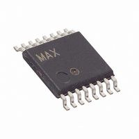
DS1882E-050+T&R Maxim Integrated Products, DS1882E-050+T&R Datasheet

DS1882E-050+T&R
Specifications of DS1882E-050+T&R
Related parts for DS1882E-050+T&R
DS1882E-050+T&R Summary of contents
Page 1
... C*-Compatible Serial Interface ♦ Three Address Pins Allow Devices Bus ♦ 45kΩ Potentiometer End-to-End Resistance ♦ Industrial Temperature Range (-40°C to +85°C) Applications ♦ 16-Pin TSSOP or SO Package PART DS1882E-050 DS1882E-050+T&R -40°C to +85° SCL DS1882Z-050+ 13 SDA 12 CE DS1882Z-050+T&R -40°C to +85°C ...
Page 2
Dual Log Audio Digital Potentiometer ABSOLUTE MAXIMUM RATINGS Voltage SDA, and SCL Relative to GND .....-0.5V to +6. Relative Voltage on A2, A1, A0, and to GND .................-0. 0.5V), not to exceed ...
Page 3
Dual Log Audio Digital Potentiometer ANALOG POTENTIOMETER CHARACTERISTICS (V = +4.5V to +5.5V +4.5V to +7.0V -4.5V to -7.0V PARAMETER End-to-End Resistance End-to-End Resistance Tolerance Ratiometric Temperature Coefficient End-to-End Resistance Temperature Coefficient Wiper ...
Page 4
Dual Log Audio Digital Potentiometer NV MEMORY CHARACTERISTICS (V = +4.5V to +5.5V +4.5V to +7.0V -4.5V to -7.0V PARAMETER Writes Note 1: All voltages are referenced to ground. Note 2: The value ...
Page 5
Dual Log Audio Digital Potentiometer ( +5.0V -5.0V +25°C POTENTIOMETER 1 (CONFIGURATON 2) ATTENUATION vs. SETTING 0 -20.0 -40.0 -60.0 -80.0 -100 ...
Page 6
Dual Log Audio Digital Potentiometer PIN NAME 1 GND Ground Address Inputs. Inputs A0, A1, and A2 determine the Negative Analog Voltage Supply Address Input. ...
Page 7
Dual Log Audio Digital Potentiometer Detailed Description The DS1882 is a dual-channel, digitally controlled, audio potentiometer. The Block Diagram illustrates the features of the DS1882. The following sections discuss these features in detail. Potentiometer Configurations The DS1882 potentiometers have two ...
Page 8
Dual Log Audio Digital Potentiometer Table 2. Configuration Option 2 TAP POSITION ATTENUATION (dB ...
Page 9
Dual Log Audio Digital Potentiometer Potentiometer Wiper Setting are the values of the two MSBs of the Command Byte, then the wiper settings of the poten- tiometers are to be programmed. The lower 6 LSBs of ...
Page 10
Dual Log Audio Digital Potentiometer Configuration Register entered as the value of the two MSBs of the Command Byte, then the Configuration Register modified. The three LSBs of the Configuration CONFIGURATION REGISTER Factory Default: ...
Page 11
Dual Log Audio Digital Potentiometer Interface for the DS1882 The CE pin serves as a communication enable pin. When active (CE = 0), the inputs SDA and SCL are rec- ognized by the device. If inactive (CE ...
Page 12
Dual Log Audio Digital Potentiometer Writing Command Byte Values An example of writing to the DS1882 is shown in Figure 2. The DS1882 has one write command that is used to change the Potentiometer Wiper Setting Registers and the Configuration ...
Page 13
Dual Log Audio Digital Potentiometer setup time (see Figure 4) before the next rising edge of SCL during a bit read. The device shifts out each bit of data on SDA at the falling edge of the previous SCL pulse, ...
Page 14
Dual Log Audio Digital Potentiometer Byte Write: A byte write consists of 8 bits of informa- tion transferred from the master to the slave (most sig- nificant bit first) plus a 1-bit acknowledgement from the slave to the master. The ...
Page 15
... Maxim cannot assume responsibility for use of any circuitry other than circuitry entirely embodied in a Maxim product. No circuit patent licenses are implied. Maxim reserves the right to change the circuitry and specifications without notice at any time. Maxim Integrated Products, 120 San Gabriel Drive, Sunnyvale, CA 94086 408-737-7600 ____________________ 15 © 2006 Maxim Integrated Products is a registered trademark of Dallas Semiconductor Corporation ...


