DS1869S-50 Maxim Integrated Products, DS1869S-50 Datasheet
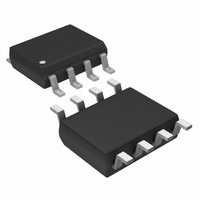
IC RHEOSTAT DALLAST 3V 50K 8SOIC

DS1869S-50

Manufacturer Part Number
DS1869S-50
Description
IC RHEOSTAT DALLAST 3V 50K 8SOIC
Manufacturer
Maxim Integrated Products
Series
Dallastat™r
Datasheet

Specifications of DS1869S-50

Taps
64
Resistance (ohms)
50K
Number Of Circuits
1
Temperature Coefficient
750 ppm/°C Typical
Memory Type
Non-Volatile
Interface
Contact Closure
Voltage - Supply
± 2.7 V ~ 8 V
Operating Temperature
-40°C ~ 85°C
Mounting Type
Surface Mount
Package / Case
8-SOIC (5.3mm Width), 8-SOP, 8-SOEIAJ
Resistance In Ohms
50K
Lead Free Status / RoHS Status
Contains lead / RoHS non-compliant
Other names
DS1869S50

Available stocks

Company
Part Number
Manufacturer
Quantity
Price
Part Number:
DS1869S-50+
Manufacturer:
Vishay
Quantity:
45 537
FEATURES
DESCRIPTION
The DS1869 Dallastat
tap points over the entire resistive range. The standard resistive ranges are 10 k , 50 k , and 100 k .
The Dallastat can be controlled by either a switch contact closure input or a digital source input such as a
CPU. The DS1869 operates from 3V or 5V supplies. Wiper position is maintained in the absence of
power through the use of a EEPROM memory cell array. The EEPROM cell array will withstand more
than 50,000 writes.
The DS1869 is offered in two standard IC packages which include an 8-pin 300-mil DIP and an 8-pin
208-mil SOIC. The DS1869 can be configured to operate using a single pushbutton, dual pushbutton or
digital source input by varying power-on conditions. This is illustrated in Figures 1 and 2. The DS1869
pinouts allow access to both ends of the potentiometer R
the digital source input, D, the up contact input, UC, and the down contact input, DC. Other pins include
the positive, +V, and negative, -V, supply inputs. The DS1869 is specified to operate from -40°C to
+85°C.
www.dalsemi.com
Replaces mechanical variable resistors
Operates from 3V or 5V supplies
Electronic interface provided for digital as
well as manual control
Internal pull-ups with debounce for easy
interfacing to mechanical push buttons
Wiper position is maintained in the absence of
power
Low cost alternative to mechanical controls
Applications include volume, tone, contrast,
brightness, and dimmer control
8-pin SOIC and 8-pin DIP packages are
available
Standard resistance values for Dallastat
-
-
-
Operating temperature range:
- Industrial: -40 C to +85 C
3V to 8V differential supply operational range
DS1869-10 ~ 10 k
DS1869-50 ~ 50 k
DS1869-100 ~ 100 k
TM
is a digital rheostat or potentiometer. This device provides 64 possible uniform
1 of 8
PIN ASSIGNMENT
PIN DESCRIPTION
R
R
R
-V, +V
UC
D
DC
L
H
W
L
, R
3V Dallastat
H
, and the wiper, R
(R
(R
(R
(R
UC
UC
H
D
H
L
D
L
)
)
)
)
See Mech. Drawings Section
- High Terminal of Potentiometer
- Wiper Terminal of Potentiometer
- Low Terminal of Potentiometer
- Voltage Supply Inputs
- Up Contact Input
- Digital Input
- Down Contact Input
8-Pin SOIC (208-mil)
8-Pin DIP (300-mil)
1
2
3
4
1
2
3
4
Digital Rheostat
W
TM
. Control inputs include
8
7
6
5
8
7
6
5
Electronic
+V
DC
(R
V-
+V
DC
(R
V-
DS1869
W
W
)
)
112099

Related parts for DS1869S-50

DS1869S-50 Summary of contents

Page 1

FEATURES Replaces mechanical variable resistors Operates from supplies Electronic interface provided for digital as well as manual control Internal pull-ups with debounce for easy interfacing to mechanical push buttons Wiper position is maintained in the absence ...

Page 2

OPERATION The DS1869 can be configured to operate from a single contact closure, dual contact closure digital source input. Figures 1 and 2 illustrate both contact closure configurations. Contact closure is defined as a transition from a high ...

Page 3

In dual pushbutton mode, each direction is controlled by the up contact (UC) and down contact (DC) inputs, respectively. No wait states are required to change wiper direction in dual pushbutton mode. In dual pushbutton mode, as the wiper position ...

Page 4

DS1869 DUAL PORT CONFIGURATION (TYPICAL EXAMPLE) Figure 2B The DS1869 is provided with two supply inputs -V and +V. The maximum voltage difference between the two supply inputs is +8.0 volts. The minimum voltage difference is +2.7 volts. All input ...

Page 5

FLOWCHART: ONE-BUTTON OPERATION AND ELECTRICAL CONTROL Figure 3 CONTACT OPEN AND CONTACT CLOSURE TIMING IS 1 SECOND 15 DS1869 ...

Page 6

FLOWCHART: TWO-BUTTON OPERATION Figure 4 CONTACT OPEN AND CONTACT CLOSURE TIMING IS 1 SECOND 15 DS1869 ...

Page 7

ABSOLUTE MAXIMUM RATINGS* Voltage on Any Pin Relative to -V Operating Temperature Storage Temperature Soldering Temperature * This is a stress rating only and functional operation of the device at these or any other conditions above those indicated in the ...

Page 8

TIMING DIAGRAMS Figure 5 NOTES: 1. All inputs; UC, DC, and D are internally pulled up with a typical resistance of 100 Input logic levels are referenced to - the internal current that flows ...

Related keywords