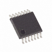
MAX5489EUD+T Maxim Integrated Products, MAX5489EUD+T Datasheet - Page 8

MAX5489EUD+T
Manufacturer Part Number
MAX5489EUD+T
Description
IC POT DGTL DUAL 256-TAP 14TSSOP
Manufacturer
Maxim Integrated Products
Datasheet
1.MAX5488EUD.pdf
(13 pages)
Specifications of MAX5489EUD+T
Taps
256
Resistance (ohms)
100K
Number Of Circuits
2
Temperature Coefficient
35 ppm/°C Typical
Memory Type
Non-Volatile
Interface
SPI, 3-Wire Serial
Voltage - Supply
2.7 V ~ 5.25 V
Operating Temperature
-40°C ~ 85°C
Mounting Type
Surface Mount
Package / Case
14-TSSOP
Resistance In Ohms
100K
Lead Free Status / RoHS Status
Lead free / RoHS Compliant
The MAX5487/MAX5488/MAX5489 contain two resistor
arrays, with 255 resistive elements each. The MAX5487
has an end-to-end resistance of 10kΩ, while the
MAX5488 and MAX5489 have resistances of 50kΩ and
100kΩ, respectively. The MAX5487/MAX5488/MAX5489
allow access to the high, low, and wiper terminals on
both potentiometers for a standard voltage-divider con-
figuration. Connect the wiper to the high terminal, and
connect the low terminal to ground, to make the device
a variable resistor (see Figure 1).
A simple 3-wire serial interface programs either wiper
directly to any of the 256 tap points. The nonvolatile
memory stores the wiper position prior to power-down
and recalls the wiper to the same point upon power-up
or by using an interface command (see Table 1). The
nonvolatile memory is guaranteed for 200,000 wiper
store cycles and 50 years for wiper data retention.
The MAX5487/MAX5488/MAX5489 use a 3-wire SPI-
compatible serial data interface (Figures 2 and 3). This
write-only interface contains three inputs: chip-select
Dual, 256-Tap, Nonvolatile, SPI-Interface,
Linear-Taper Digital Potentiometers
8
5, 6, 9
TQFN
8, 16
_______________________________________________________________________________________
10
11
12
13
14
15
—
1
2
3
4
7
PIN
TSSOP
7, 9, 10
14
13
12
11
—
—
8
6
5
4
3
2
1
NAME
SCLK
GND
N.C.
V
DIN
I.C.
WB
WA
CS
HB
HA
LB
LA
EP
DD
Detailed Description
Power Supply. Bypass V
Serial-Interface Clock Input
Serial-Interface Data Input
Active-Low Chip-Select Digital Input
No Connection. Not internally connected.
Ground
Internally connected to EP. Leave unconnected.
Low Terminal of Resistor B. The voltage at L can be greater than or less than the voltage at H.
Current can flow into or out of L.
Wiper Terminal of Resistor B
High Terminal of Resistor B. The voltage at H can be greater than or less than the voltage at L.
Current can flow into or out of H.
Low Terminal of Resistor A. The voltage at L can be greater than or less than the voltage at H.
Current can flow into or out of L.
Wiper Terminal of Resistor A
High Terminal of Resistor A. The voltage at H can be greater than or less than the voltage at L.
Current can flow into or out of H.
Exposed Pad (TQFN only). Internally connected to pins 8 and 16. Leave unconnected.
SPI Digital Interface
DD
to GND with a 0.1µF capacitor as close to the device as possible.
(CS), data clock (SCLK), and data in (DIN). Drive CS low
to enable the serial interface and clock data synchro-
nously into the shift register on each SCLK rising edge.
The WRITE commands (C1, C0 = 00 or 01) require 16
clock cycles to clock in the command, address, and data
(Figure 3a). The COPY commands (C1, C0 = 10, 11) can
use either eight clock cycles to transfer only command
and address bits (Figure 3b) or 16 clock cycles, with the
device disregarding 8 data bits (Figure 3a).
After loading data into the shift register, drive CS high
to latch the data into the appropriate potentiometer
control register and disable the serial interface. Keep
CS low during the entire serial data stream to avoid cor-
ruption of the data.
The data format consists of three elements: command
bits, address bits, and data bits (see Table 1 and
Figure 3). The command bits (C1 and C0) indicate the
action to be taken such as changing or storing the
wiper position. The address bits (A1 and A0) specify
which potentiometer the command affects and the 8
data bits (D7 to D0) specify the wiper position.
FUNCTION
Digital-Interface Format
Pin Description


