1462050-1 TE Connectivity, 1462050-1 Datasheet
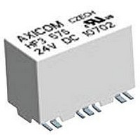
RF SIGNAL RELAY, SPDT, 3VDC, 2A, PC BOARD

1462050-1

Manufacturer Part Number
1462050-1
Description
RF SIGNAL RELAY, SPDT, 3VDC, 2A, PC BOARD
Manufacturer
TE Connectivity
Type
Signal Relayr
Datasheet

Specifications of 1462050-1

Coil Type
DC
Contact Configuration
SPCO
Contact Current Max
2A
Contact Voltage Ac Nom
250V
Contact Voltage Dc Nom
220V
Coil Voltage Vdc Nom
3V
Coil Resistance
64ohm
Rohs Compliant
Yes
Relay Construction
Non-Latching
Contact Arrangement
SPDT
Coil Voltage Dc
3V
Coil Current
46.8mA
Contact Form
1 Form C
Voltage Rating (vdc)
220V
Voltage Rating (vac)
250V
Dropout Volt (min)
0.3VDCV
Pick-up Voltage (max)
2.25VDC
Maximum Power Rating
60W/62.5VA
Operate Time
3ms
Contact Current Rating
2A
Coil Suppression Diode
No
Push To Test Button
No
Led Indicator
No
Seal
Sealed
Product Height (mm)
10mm
Product Depth (mm)
9.4mm
Product Length (mm)
14.6mm
Operating Temp Range
-55C to 85C
Pin Count
16
Mounting Style
Surface Mount
Termination Style
Gull Wing
Lead Free Status / Rohs Status
Compliant
n
n
n
n
n
n
n
Typical applications
Cable modems and linecards/ CATV, Tabs, measurement and test
equipment ATE, satellite / audio / video tuners, wireless base stations and
antennas, switching boards
10-2010, Rev. 1010
www.tycoelectronics.com
© 2010 Tyco Electronics Ltd.
75Ω version, monostable, 1 coil
Contact Data
Contact arrangement
Max. switching voltage
Rated current
Limiting continuous current, 23°C
Switching power
Max. continuos RF-power, 23°C
Contact material
Minimum switching voltage
Initial contact resistance
Operate time
Release time
Bounce time
Mechanical endurance
Coil Data
Coil voltage range
Coil versions, monostable
50Ω version, monostable, 1 coil
All figures are given for coil without pre-energization, at ambient temperature +23°C.
Coil
code
51
52
53
54
55
56
57
01
02
03
04
05
06
07
Y-Design
Frequency range DC to 3GHz
Impedance 50Ω or 75Ω
Small dimensions (14.6x7.2x10mm)
1 form C contact (1 changeover contact)
Immersion cleanable
Low power consumption (≤140mW)
without diode in parallel
with diode in parallel
voltage
Rated
VDC
4.5
4.5
12
24
12
24
3
5
6
9
3
5
6
9
Operate
voltage
18.00
18.00
VDC
2.25
3.38
3.75
4.50
6.75
9.00
2.25
3.38
3.75
4.50
6.75
9.00
Limiting
voltage
10.90
13.00
19.60
26.10
52.30
10.90
13.00
19.60
26.10
52.30
VDC
6.50
9.80
6.50
9.80
RF Signal Relays
HF3 Relay
Datasheets and product specification ac-
cording to IEC 61810-1 and to be used only
together with the ‘Definitions’ section.
<100mΩ at 10mA, 20mV
Release
typ. 3ms, max. 5ms
typ. 2ms, max. 5ms
typ. 4ms, max. 6ms
typ. 1ms, max. 3ms
voltage
220VDC, 250VAC
VDC
0.30
0.45
0.50
0.60
0.90
1.20
2.40
0.30
0.45
0.50
0.60
0.90
1.20
2.40
1 form C, 1 CO
Ag, Au covered
10
50W (2.5GHz)
50W (2.5GHz)
60W, 62.5VA,
3 to 24VDC
7
100µV
operations
2A
2A
resistance
Ω±10%
4114
1028
4114
1028
145
178
257
574
145
178
257
574
Coil
64
64
Rated coil
power
mW
140
140
140
140
140
140
140
140
140
140
140
140
140
140
Datasheets and product data is subject to the
terms of the disclaimer and all chapters of
the ‘Definitions’ section, available at
http://relays.tycoelectronics.com/definitions
Coil Data
Coil versions, bistable
50Ω version, bistable, 1 coil
50Ω version, bistable, 2 coils
All figures are given for coil without pre-energization, at ambient temperature +23°C.
93
94
95
96
97
Coil
code
71
72
73
74
75
76
77
91
92
140 mW
Unom =
Umax. =
U
U
All specifications subject to change. Consult Tyco Electronics for latest specifications.
Coil Operating Range
op. min.
rel. min.
voltage
Rated
VDC
(continued)
4.5
4.5
12
24
12
24
3
5
6
9
3
5
6
9
=
=
U
nom.
Nominal coil voltage
Upper limit of the operative range of
the coil voltage (limiting voltage)
Lower limit of the operative range of
the coil voltage (reliable operate voltage)
For latching relays Uset min. resp. Ureset min.
Lower limit of the operative range of
the coil voltage (reliable release voltage)
voltage
18.00
18.00
nominal coil voltage
VDC
2.25
3.38
3.75
4.50
6.75
9.00
2.25
3.38
3.75
4.50
6.75
9.00
Set
Ambient Temperature [°C]
U
U
op. min.
rel. min.
Limiting
voltage
13.85
15.30
18.50
27.70
37.00
74.00
10.90
13.00
19.60
26.10
52.30
VDC
9.20
6.50
9.80
Datasheets, product data, ‘Definitions’ sec-
tion, application notes and all specifications
are subject to change.
-18.00
U
voltage
18.00
-2.25
-3.38
-3.75
-4.50
-6.75
-9.00
Reset
VDC
2.25
3.38
3.75
4.50
6.75
9.00
max.
at 0 A
resistance
Ω±10%
Contacts in reset position.
sition might change during
tion and must be reset bef
140 mW
1157
2057
8228
1028
4114
128
289
357
514
145
178
257
574
Coil
64
Axicom
Rated coil
power
mW
140
140
140
140
140
140
140
70
70
70
70
70
70
70
1
70 m

Related parts for 1462050-1

1462050-1 Summary of contents

Page 1

... VDC VDC VDC = Lower limit of the operative range of op. min. the coil voltage (reliable operate voltage) 3 2.25 9.20 -2.25 For latching relays Uset min. resp. Ureset min. 4.5 3.38 13.85 -3.38 = Lower limit of the operative range of 5 3.75 15.30 -3.75 rel. min. ...

Page 2

... RF Signal Relays HF3 Relay Coil Data (continued) Coil versions, bistable Coil Rated Set Limiting code voltage voltage voltage VDC VDC VDC 75Ω version, bistable, 1 coil 21 3 2.25 9.20 22 4.5 3.38 13. 3.75 15. 4.50 18. 6.75 27. 9.00 37. 18.00 74.00 75Ω version, bistable, 2 coils ...

Page 3

... RF Signal Relays HF3 Relay Typical RF performance, 50Ω version (continued) 0.1 0.0 -0.1 -0.2 -0.3 -0.4 0 500 1000 1500 Frequency [Mhz] 1.25 1.20 1.15 1.10 1.05 1.00 0 500 1000 1500 Frequency[Mhz] Terminal assignment TOP view on component side of PCB Monostable 10-2010, Rev. 1010 ...

Page 4

... RF Signal Relays HF3 Relay PCB layout TOP view on component side of PCB 50Ω version Dimensions 50Ω version 4 10-2010, Rev. 1010 Datasheets and product specification ac- cording to IEC 61810-1 and to be used only www.tycoelectronics.com together with the ‘Definitions’ section. © 2010 Tyco Electronics Ltd. ...

Page 5

... RF Signal Relays HF3 Relay Processing Recommended soldering conditions Vapour phase soldering 20 to 40s 240°C 180°C 130°C external preheating 100°C Recommended reflow soldering profile Infrared soldering temperature/time profile (lead and housing peak temp.) Resistance to soldering heat Infrared soldering temperature/time profi ...

Page 6

... Monostable 1462050-1 1-1462050-6 1462050-2 1-1462050-7 1462050-3 1462050-4 1462050-5 Bistable 1 coil 1462050-6 1-1462050-8 1462050-7 1-1462050-9 1462050-8 1462050-9 1-1462050-0 Bistable 2 coils 1-1462050-1 2-1462050-0 1-1462050-2 2-1462050-1 1-1462050-3 1-1462050-4 1-1462050-5 Datasheets, product data, ‘Definitions’ sec- tion, application notes and all specifications are subject to change. ...

Related keywords