IM47NS TE Connectivity, IM47NS Datasheet
IM47NS
Specifications of IM47NS


Related parts for IM47NS


IM47NS Summary of contents
Page 1
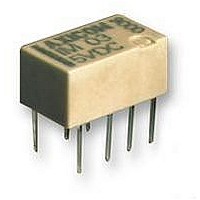
... IM Series AXICOM Signal and Telecom Relays ...
Page 2
... AXICOM Telecom, Signal and RF Relays IM Relay UL 508 File No. E 111441 UL 60950 IEC/EN60950 IEC Ref. Cert. No. 3270 All specifications subject to change. Consult Tyco Electronics for latest specifications. Disclaimer While Tyco Electronics and its affiliates referenced herein have made every reasonable effort to ensure the accuracy of the information contained in this catalog, Tyco Electro- nics cannot assure that this information is error free ...
Page 3
... AXICOM Telecom, Signal and RF Relays IM Relay IM Relay 1 and 2 pole telecom/signal relay, polarized Through Hole Types (THT), standard version with 5.08 mm, narrow with 3.2 mm between the terminal rows or Surface Mount Type (SMT) Relay Types: non – latching with 1 coil latching with 1 coil ...
Page 4
... AXICOM Telecom, Signal and RF Relays IM Relay Selection Guide IM-A IM-B 1 Pole break 1 Pole make 1 Form B 1 Form A SPST NC SPST NO IM-A High Dielectric “C” Relay Code IM All specifications subject to change. Consult Tyco Electronics for latest specifications. IM Relay IM Relay IM Pole changeover 2 Pole changeover ...
Page 5
... AXICOM Telecom, Signal and RF Relays IM Relay 2 Pole Changeover / 2 Form C / DPDT Dimensions IM THT Standard mm inch L 10.00 ± 0.08 0.393 ± 0.003 W 6.00 ± 0.08 0.236 ± 0.003 H 5.65 – 0.20 0.222 – 0.008 T 3.2 0.125 T1 N/A N/A T2 5.08 ± 0.10 0.200 ± 0.004 D1 3.20 ± ...
Page 6
... AXICOM Telecom, Signal and RF Relays IM Relay 2 Pole Changeover / 2 Form C / DPDT Coil Data (values at 23 °C) Nominal Operate/set voltage range voltage U nom Minimum Maximum voltage U voltage U min Vdc Vdc Standard Version THT Standard non-latching 1 coil 1.5 1.13 3 2.25 4.5 3.38 5 3. ...
Page 7
... IM40NS 1-1462038-8 90 IM41NS 1-1462038-9 203 IM42NS 2-1462038-0 250 IM43NS 2-1462038-1 360 IM44NS 2-1462038-2 810 IM45NS 2-1462038-3 1440 IM46NS 2-1462038-4 2880 IM47NS 2-1462038-5 23 IM40JR 5-1462037-2 90 IM41JR 5-1462037-5 203 IM42JR 5-1462037-7 250 IM43JR 6-1462037-0 360 IM44JR 6-1462037-3 810 IM45JR 6-1462037-5 1440 IM46JR 6-1462037-8 ...
Page 8
... AXICOM Telecom, Signal and RF Relays IM Relay 2 Pole Changeover / 2 Form C / DPDT Coil Data (values at 23 °C) Nominal Operate/set voltage range voltage U nom Minimum Maximum voltage U voltage U min Vdc Vdc High Sensitive Version SMT Gull Wings non-latching 1 coil 3 2.40 4.5 3.60 5 4. ...
Page 9
... AXICOM Telecom, Signal and RF Relays IM Relay 2 Pole Changeover / 2 Form C / DPDT Coil Data (values at 23 °C) Nominal Operate/set voltage range voltage U nom Minimum Maximum voltage U voltage U min Vdc Vdc Ultra High Sensitive Version SMT Gull Wings non-latching 1 coil 3 2.55 4.5 3. ...
Page 10
... AXICOM Telecom, Signal and RF Relays IM-A Relay 1 Pole Break / 1 Form B / SPST NC Dimensions IM-A THT Version Standard Version Mounting Hole Layout View onto the component side of the PCB (top view) Terminal Assignment Relay – top view Non-Latching Type not energized condition All specifications subject to change. Consult Tyco Electronics for latest specifications. ...
Page 11
... AXICOM Telecom, Signal and RF Relays IM-A Relay 1 Pole Break / 1 Form B / SPST NC Coil Data (values at 23 °C) Nominal Operate/set voltage range voltage U nom Minimum Maximum voltage U voltage U min Vdc Vdc IM-A SMT Gull Wings non-latching 1 coil 3 2.25 4.5 3.38 5 3.75 12 9.00 THT non-latching 1 coil 3 2 ...
Page 12
... AXICOM Telecom, Signal and RF Relays IM-B Relay 1 Pole Make / 1 Form A / SPST NO Dimensions IM-B THT Version Standard Version Mounting Hole Layout View onto the component side of the PCB (top view) Terminal Assignment Relay – top view Non-Latching Type not energized condition All specifications subject to change. Consult Tyco Electronics for latest specifications. ...
Page 13
... AXICOM Telecom, Signal and RF Relays IM-B Relay 1 Pole Make / 1 Form A / SPST NO Coil Data (values at 23 °C) Nominal Operate/set voltage range voltage U nom Minimum Maximum voltage U voltage U min Vdc Vdc IM-B SMT Gull Wings non-latching 1 coil 3 2.25 4.5 3.38 5 3.75 6 4. ...
Page 14
... AXICOM Telecom, Signal and RF Relays IM-C Relay 1 Pole Changeover / 1 Form C / SPDT Dimensions IM-C THT Version Standard Version Mounting Hole Layout View onto the component side of the PCB (top view) Terminal Assignment Relay – top view Non-Latching Type not energized condition All specifications subject to change. Consult Tyco Electronics for latest specifications. ...
Page 15
... AXICOM Telecom, Signal and RF Relays IM-C Relay 1 Pole Changeover / 1 Form C / SPDT Coil Data (values at 23 °C) Nominal Operate/set voltage range voltage U nom Minimum Maximum voltage U voltage U min Vdc Vdc IM-C SMT Gull Wings non-latching 1 coil 3 2.25 4.5 3.38 5 3.75 12 9.00 24 18.00 ...
Page 16
... AXICOM Telecom, Signal and RF Relays IM-D Relay 2 Pole Break / 2 Form B / DPST NC Dimensions IM-D THT Version Standard Version Mounting Hole Layout View onto the component side of the PCB (top view) Terminal Assignment Relay – top view Non-Latching Type not energized condition All specifications subject to change. Consult Tyco Electronics for latest specifications. ...
Page 17
... AXICOM Telecom, Signal and RF Relays IM-D Relay 2 Pole break / 2 Form B / DPST NC Coil Data (values at 23 °C) Nominal Operate/set voltage range voltage U nom Minimum Maximum voltage U voltage U min Vdc Vdc IM-D SMT Gull Wings non-latching 1 coil 3 2.25 4.5 3.38 5 3.75 12 9.00 THT non-latching 1 coil 3 2 ...
Page 18
... AXICOM Telecom, Signal and RF Relays IM-E Relay 2 Pole Make / 2 Form A / DPST NO Dimensions IM-E THT Version Standard Version Mounting Hole Layout View onto the component side of the PCB (top view) Terminal Assignment Relay – top view Non-Latching Type not energized condition All specifications subject to change. Consult Tyco Electronics for latest specifications. ...
Page 19
... AXICOM Telecom, Signal and RF Relays IM-E Relay 2 Pole Make / 2 Form A / DPST NO Coil Data (values at 23 °C) Nominal Operate/set voltage range voltage U nom Minimum Maximum voltage U voltage U min Vdc Vdc IM-E SMT Gull Wings non-latching 1 coil 3 2.25 4.5 3.38 5 3.75 12 9.00 THT non-latching 1 coil 3 2 ...
Page 20
... AXICOM Telecom, Signal and RF Relays IM Relay 2 Pole Changeover / 2 Form C / DPDT Contact Data Number of contacts and type Contact assembly Contact material Limiting continuous current at max. ambient temperature Maximum switching current Maximum swichting voltage Maximum switching capacity Thermoelectric potential Minimum switching voltage Initial contact resistance / ...
Page 21
... AXICOM Telecom, Signal and RF Relays IM Relay Contact Data Number of contacts and type Contact assembly Contact material Limiting continuous current at max. ambient temperature Maximum switching current Maximum swichting voltage Maximum switching capacity Thermoelectric potential Minimum switching voltage Initial contact resistance / measuring condition ...
Page 22
... AXICOM Telecom, Signal and RF Relays IM Relay Insulation IM Versions Insulation resistance at 500 Vdc Dielectric test voltage (1 min) between coil and contacts between adjacent contact sets between open contacts Surge voltage resistance according to Telcordia TR-NWT-001089 (2/10 µs) between coil and contacts between adjacent contact sets between open contacts according / EC 60950 (10/ 700 µ ...
Page 23
... AXICOM Telecom, Signal and RF Relays IM Relay High Frequency Data Capacitance between coil and contacts between adjacent contact sets between open contacts RF Characteristics Isolation at 100 MHz / 900 MHz Insertion loss at 100 MHz / 900 MHz V.S.W.R. at 100 MHz / 900 MHz General Data Operate time at U typ ...
Page 24
... Upper limit of the operative range of the coil voltage (limiting voltage) when coils are continously energized = Lower limit of the operative range of the coil voltage (reliable operate voltage) For latching relays Uset min. resp. Ureset min. = Lower limit of the operative range of the coil voltage (reliable release voltage ...
Page 25
... AXICOM Telecom, Signal and RF Relays IM Relay Recommended Soldering Conditions Soldering conditions according IEC 60058-2-58 and IPC/JEDEC J-STD-020B sec 240 °C 180 °C 130 °C 100 °C Time (s) Recommended Reflow Soldering Profile Time (s) Resistance to Soldering Heat - Reflow Profile Time (s) All specifications subject to change. Consult Tyco Electronics for latest specifications. ...
Page 26
... AXICOM Telecom, Signal and RF Relays IM Relay Packing Reel Dimension All specifications subject to change. Consult Tyco Electronics for latest specifications. 108-98001 Rev. K Dimensions in mm Tube for THT version 50 relays per tube 1‘000 relays per box Tape and reel for SMT version 1’000 relays per reel 1’ ...
Page 27
... Nominal voltage range from 5 ... 24 V, coil power consumption 50...280 mW for 1 n/o and 125 ... 280 mW for 2 n c/o versions. Reedrelays are available in DIP or SIL housing and capable to switch currents up to 0,5 A. Integrated diode and/or electrostatic shield optional. Dielectric strength 1500 Vdc. Dimen- sions approx ...
Page 28
Tyco Electronics Corporation POB 3608, Harrisburg, PA 17105 USA Phone +1 800-522-6752 www.tycoelectronics.com 108-98001 • Jul. 09 Rev. K • ECOC: JM10 Tyco Electronics Logistics AG Werk Axicom Au Seestrasse 295 CH-8804 Au-Wädenswil / Switzerland Phone +41 44 782 91 ...