704.918.4 EAO, 704.918.4 Datasheet - Page 80
704.918.4
Manufacturer Part Number
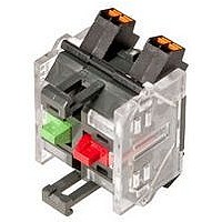
704.918.4
Description
Slow-make Switching Element, 2NC, Push-In Terminals, Silver
Manufacturer
EAO
Datasheet
1.704-6311.pdf
(130 pages)
Specifications of 704.918.4
Contact Configuration
DPST-NC
Microswitch Type
Snap Action
Contact Voltage Ac Nom
250V
Contact Current Max
6A
Switch Terminals
Plug-In
Circuitry
DPST-NC
Features
Slow-Make


Technical Data
>
Switching system
Material
Mechanical characteristics
0
Electrical characteristics
Slow-make switching element
Declaration of conformity
CE
The double-break, slow-make switching element is equipped with
one or two independent contact systems, acting as normally open
or normally closed contact. The normally closed contact has forced
opening.
Slow-make contacts with forced action are ideal for high switch
ratings.
Up to three switching elements can be snapped to each actuator.
For the emergency-stop pushbutton use the slow-make switching
element (max. 2).
Material of contact
Hardsilver, gold-silver, silver-palladium (for aggressive
atmospheres)
Switch housing
Polycarbonate (PC)
Terminals
Screw terminals
Plug-in terminals 6.3 x 0.8 mm
max. wire cross-section 2 x 2.5 mm²
max. wire cross-section of stranded cable 2 x 1.5 mm²
For switches with plug-in terminals it is necessary to provide
insulation sleeves and to maintain a spacing of 65 mm between
rows (mounting dimensions)
Tightening torque
Screws at the mounting flange max. 25 Ncm
Screws at switching element max. 50 Ncm
Actuating force
1 Normally closed 2 N
1 Normally open 3.1 N
Actuating travel
5.8 mm ± 0.2 mm
Rebound time
≤1 ms
Mechanical lifetime
(with 1 switching element)
Pushbutton maintained action
Pushbutton momentary action
Selector switch maintained action 1.25 million Cycles of operation
Selector switch momentary action 2.5 million
Emergency-stop switch
Keylock switch maintained action 25 000
Keylock switch momentary action 50 000
Standards
The switches comply with the "Standards for low-voltage switching
devices" EN IEC 60947-5-1
Rated Insulation Voltage U
500 VAC / 600 VDC, as per EN IEC 60947-5-1
78
07.2010
i
1.5 million
3 million
50 000
Cycles of operation
Cycles of operation
Cycles of operation
Cycles of operation
Cycles of operation
Cycles of operation
0
0
0
0
Environmental conditions
Approvals
Contact resistance
New state ≤50 mΩ as per DIN IEC 60512-2-4
Isolation resistance
≥10 MΩ between open contacts at 500 VDC, as per DIN IEC 60512-
2-10
Electrical life
50 000 cycles of operations
Conventional free air thermal current I
10 A, as per EN IEC 60947-5-1
the maximum current in continuous operation and at ambient
temperature must not exceed the quoted maximum values.
Switch rating
At switch rating AC for gold-silver, silver-palladium and hardsilver
contacts, service category AC-15, as per EN IEC 60947-5-1 (cosφ
0.3)
Voltage
Current
At switch rating DC for gold-silver and hardsilver contacts, service
category DC-13, as per EN IEC 60947-5-1
Voltage
Current
Recommended minimum operational data
Gold-silver contacts:
Voltage
Current
Hardsilver contacts:
Voltage
Current
Protection class
Indicators and switches, fit for mounting into devices with protection
class II
Storage temperature
-40 °C ... +85 °C
Operating temperature
-40 °C ... +55 °C
Protection degree
IP 20
Shock resistance
(single impacts, semi-sinusoidal)
300 m/s²puls width 11 ms, as per EN IEC 60068-2-27
Vibration resistance
(sinusoidal)
100 m/s² at 10 Hz ... 500 Hz, amplitude 0,75 mm, as per EN IEC
60068-2-6
Approbations
CB (IEC 60947)
CCC
CSA
Germanischer Lloyd
GOST
NFF 16-102
230 VAC
7 A
24 VDC
10 A
24 VDC
10 mA
24 VDC
50 mA
60 VDC
5 A
110 VDC
2 mA
110 VDC
10 mA
400 VAC
5 A
110 VDC
2.5 A
500 VAC
4 A
th
250 VDC
0.6 A
04
Related parts for 704.918.4
Image
Part Number
Description
Manufacturer
Datasheet
Request
R

Part Number:
Description:
Indicator
Manufacturer:
EAO
Datasheet:


Part Number:
Description:
Switch Actuator
Manufacturer:
EAO
Datasheet:

Part Number:
Description:
Switch Actuator
Manufacturer:
EAO
Datasheet:
Part Number:
Description:
Switch Actuator
Manufacturer:
EAO
Datasheet:
Part Number:
Description:
Switch Actuator
Manufacturer:
EAO
Datasheet:


Part Number:
Description:
SINGLE CHIP LED/ T1 BI-PIN/ 2.1VDC/20MA - RED
Manufacturer:
EAO
Datasheet:

Part Number:
Description:
INDICATOR, INCAND LAMP, BI PIN
Manufacturer:
EAO
Datasheet:

Part Number:
Description:
INDICATOR, BI-PIN
Manufacturer:
EAO
Datasheet:

Part Number:
Description:
INDICATOR, INCAND LAMP, MIDGET GROOVED
Manufacturer:
EAO
Datasheet: