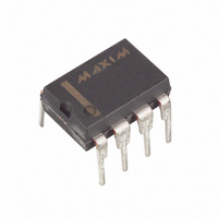
DS1669-10+ Maxim Integrated Products, DS1669-10+ Datasheet - Page 5

DS1669-10+
Manufacturer Part Number
DS1669-10+
Description
IC RHEOSTAT DALLASTAT 10K 8-DIP
Manufacturer
Maxim Integrated Products
Series
Dallastat™r
Datasheet
1.DS1669-50.pdf
(11 pages)
Specifications of DS1669-10+
Taps
64
Resistance (ohms)
10K
Number Of Circuits
1
Temperature Coefficient
750 ppm/°C Typical
Memory Type
Non-Volatile
Interface
Contact Closure
Operating Temperature
-40°C ~ 85°C
Mounting Type
Through Hole
Package / Case
8-DIP (0.300", 7.62mm)
Resistance In Ohms
10K
Lead Free Status / RoHS Status
Lead free / RoHS Compliant
Voltage - Supply
-
DS1669
DS1669 DUAL PUSHBUTTON CONFIGURATION (TYPICAL APPLICATION)
Figure 2B
The DS1669 is provided with two supply inputs -V and +V. The maximum voltage difference between
the two supply inputs is +8.0 volts. The minimum voltage difference is +4.5 volts. All input levels are
referenced to the negative supply input, -V. The voltage applied to any Dallastat terminal must not exceed
the negative supply voltage (-V ) by -0.5 or the positive supply voltage (+V) by +0.5 volts. The minimum
logic high level must be +2.4 volts with reference to the -V supply voltage input for +V=5V. A logic low
level with reference to the -V supply voltage has a maximum value of +0.8 volts. Dallastats exhibit a
typical wiper resistance of 400 ohms with a maximum wiper resistance of 1000 ohms. The maximum
wiper current allowed through the Dallastat is specified at 1 milliamps (see DC Electrical
Characteristics).
NONVOLATILE WIPER SETTINGS
Dallastats maintain the position of the wiper in the absence of power. This feature is provided through the
use of EEPROM type memory cell arrays. During normal operation the position of the wiper is
determined by the input multiplexer. Periodically, the multiplexer will update the EEPROM memory
cells. The manner in which an update occurs has been optimized for reliability, durability, and
performance. Additionally, the update operation is totally transparent to the user.
When power is applied to the Dallastat, the wiper setting will be the last recorded in the EEPROM
memory cells. If the Dallastat setting is changed after power is applied, the new value will be stored after
a delay of 2 seconds. The initial storage of a new value after power-up occurs when the first change is
made, regardless of when this change is made.
After the initial change on power-up, subsequent changes in the Dallastat EEPROM memory cells will
occur only if the wiper position of the part is moved greater than 12.5% of the total resistance range. Any
wiper movement after initial power-up which is less than 12.5% will not be recorded in the EEPROM
memory cells. Since the Dallastat contains a 64-to-1 multiplexer, a change of greater than 12.5%
corresponds to a change of the fourth LSB.
Changes or storage to the EEPROM memory cells must allow for a 2-second delay to guarantee that
updates will occur. The EEPROM memory cells are specified to accept greater than 80,000 writes before
a wear-out condition. If the EEPROM memory cells do reach a wear-out condition, the Dallastat will still
function properly while power is applied. However, on power-up the device’s wiper position will be that
of the position last recorded before memory cell wear-out.
5 of 10


