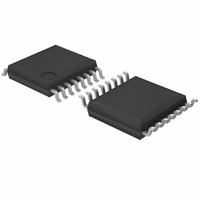
BH2223FV-E2 Rohm Semiconductor, BH2223FV-E2 Datasheet - Page 6

BH2223FV-E2
Manufacturer Part Number
BH2223FV-E2
Description
IC CONV D/A 8BIT 10CH SSOP-B16
Manufacturer
Rohm Semiconductor
Series
-r
Specifications of BH2223FV-E2
Data Interface
Serial
Number Of Bits
8
Number Of Converters
10
Voltage Supply Source
Single Supply
Power Dissipation (max)
400mW
Operating Temperature
-20°C ~ 85°C
Mounting Type
Surface Mount
Package / Case
16-SSOP
Resolution (bits)
8bit
Input Channel Type
Serial
Supply Voltage Range - Analogue
2.7V To 5.5V
Supply Current
1mA
Digital Ic Case Style
SSOP
No. Of Pins
16
Operating
RoHS Compliant
Settling Time
-
Number Of Outputs And Type
10 Voltage, Unipolar
Lead Free Status / RoHS Status
Lead free / RoHS Compliant
Settling Time
-
Lead Free Status / Rohs Status
Lead free / RoHS Compliant
Other names
BH2223FV-E2
BH2223FV-E2-TR
BH2223FV-E2-TR
Available stocks
Company
Part Number
Manufacturer
Quantity
Price
Company:
Part Number:
BH2223FV-E2
Manufacturer:
ROHM
Quantity:
10 000
●Notes for use
●Thermal Derating Curve
© 2010 ROHM Co., Ltd. All rights reserved.
BH2223FV,BH2221FV
www.rohm.com
(1) Numbers and data in entries are representative design values and are not guaranteed values of the items.
(2) Although we are confident in recommending the sample application circuits, carefully check their characteristics further
(3) Absolute maximum ratings
(4) GND potential
(5) Thermal design
(6) Terminal shorts and mis-mounting
(7) Operation in a strong magnetic field
(8) Power source voltage
(9) Reset Function
①SSOP-B20(BH2221FV)
②SSOP-B16(BH2223FV)
when using them. When modifying externally attached component constants before use, determine them so that they
have sufficient margins by taking into account variations in externally attached components and the Rohm LSI, not only for
static characteristics but also including transient characteristics.
Operating or testing the device over the maximum specifications may damage the part itself as well as peripheral
components. Therefore, please ensure that the specifications are not exceeded.
Ensure that the GND terminal is at the lowest potential under all operating conditions.
Use a thermal design that allows for a sufficient margin regarding power dissipation (Pd) under actual operating
conditions.]
Incorrect orientation or misalignment of the IC when mounting to the PCB may damage part. Short-circuits caused by the
introduction of foreign matter between the output terminals or across the output and power supply or GND may also result
in destruction.
Operation in a strong electromagnetic field may cause malfunction.
Set the power source voltage so that VCC ≧ VDD.
The power on reset circuit, which initializes internal settings, may malfunction during abrupt power ons. Therefore, set
the time constant so as to satisfy the power source rise time.
Mounted on a 70x70x1.6mm FR4 glass epoxy board (copper foil area 3% or below)
700
600
500
400
300
200
100
0
0
25
①
②
50
Ta [℃]
Fig.18
75
6/7
100
125
Technical Note
2010.06 - Rev.B


