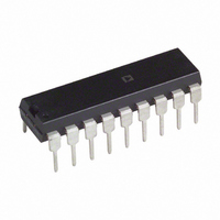
AD7541AJNZ Analog Devices Inc, AD7541AJNZ Datasheet - Page 5

AD7541AJNZ
Manufacturer Part Number
AD7541AJNZ
Description
IC DAC 12BIT MULT MONO 18-DIP
Manufacturer
Analog Devices Inc
Datasheet
1.AD7541AKRZ.pdf
(8 pages)
Specifications of AD7541AJNZ
Data Interface
Parallel
Settling Time
600ns
Number Of Bits
12
Number Of Converters
1
Voltage Supply Source
Single Supply
Operating Temperature
0°C ~ 70°C
Mounting Type
Through Hole
Package / Case
18-DIP (0.300", 7.62mm)
Resolution (bits)
12bit
Input Channel Type
Parallel
Supply Current
2mA
Digital Ic Case Style
DIP
No. Of Pins
18
Operating Temperature Range
0°C To +70°C
Lead Free Status / RoHS Status
Lead free / RoHS Compliant
Power Dissipation (max)
-
Lead Free Status / Rohs Status
RoHS Compliant part
Electrostatic Device
Available stocks
Company
Part Number
Manufacturer
Quantity
Price
Company:
Part Number:
AD7541AJNZ
Manufacturer:
SIPEX
Quantity:
13 595
REV. B
BIPOLAR OPERATION
(4-QUADRANT MULTIPLICATION)
Figure 5 and Table III illustrate the circuitry and code relation-
ship for bipolar operation. With a dc reference (positive or nega-
tive polarity) the circuit provides offset binary operation. With
an ac reference the circuit provides full 4-quadrant multiplication.
With the DAC loaded to 1000 0000 0000, adjust R1 for
V
the ratio of R3 to R4 for V
be accomplished by adjusting the amplitude of V
ing the value of R5.
As in unipolar operation, A1 must be chosen for low V
low I
ing. Mismatch of 2R3 to R4 causes both offset and full-scale
error. Mismatch of R5 to R4 or 2R3 causes full-scale error. C1
phase compensation (10 pF to 50 pF) may be required for sta-
bility, depending on amplifier used.
Binary Number in DAC
MSB
1 1 1 1
1 0 0 0
1 0 0 0
0 1 1 1
0 0 0 0
V
Table III. Bipolar Code Table for Offset Binary Circuit of
Figure 5
OUT
Figure 5. Bipolar Operation (4-Quadrant Multiplication)
IN
B
= 0 V (alternatively, one can omit R1 and R2 and adjust
. R3, R4 and R5 must be selected for matching and track-
R1
*
0 0 0 0
1 1 1 1
0 0 0 0
1 1 1 1
0 0 0 0
17
BIT 1 – BIT 12
PINS 4–15
V
REF
V
V
16
DD
DD
AD7541A
R
18
FB
LSB
1 1 1 1
0 0 0 1
0 0 0 0
1 1 1 1
0 0 0 0
GROUND
DIGITAL
GND
3
OUT
OUT1
OUT2
R2
*
= 0 V). Full-scale trimming can
1
2
COMMON
ANALOG
C1
33pF
Analog Output, V
+V
+V
0 Volts
–V
–V
A1
AD544L
IN
IN
IN
IN
*
SEE TABLE 1.
FOR VALUES OF R1 AND R2
2048
2048
2048
2047
2048
2048
10k
5k
10%
R6
R3
1
1
REF
R4
20k
or by vary-
A2
AD544J
OS
20k
R5
OUT
and
V
OUT
–5–
Figure 6 and Table IV show an alternative method of achieving
bipolar output. The circuit operates with sign plus magnitude
code and has the advantage of giving 12-bit resolution in each
quadrant, compared with 11-bit resolution per quadrant for the
circuit of Figure 5. The AD7592 is a fully protected CMOS
changeover switch with data latches. R4 and R5 should match
each other to 0.01% to maintain the accuracy of the D/A con-
verter. Mismatch between R4 and R5 introduces a gain error.
Table IV. 12-Bit Plus Sign Magnitude Code Table for Circuit
of Figure 6
Sign
Bit
0
0
1
1
Note: Sign bit of “0” connects R3 to GND.
V
IN
Figure 6. 12-Bit Plus Sign Magnitude Operation
R1
Binary Number in DAC
MSB
1 1 1 1 1 1 1 1 1 1 1 1
0 0 0 0 0 0 0 0 0 0 0 0
0 0 0 0 0 0 0 0 0 0 0 0
*
1 1 1 1 1 1 1 1 1 1 1 1
17
BIT 1 – BIT 12
PINS 4–15
V
REF
V
V
16
DD
DD
AD7541A
SIGN BIT
R
18
FB
GND
OUT1
OUT2
3
R2
DIGITAL
GROUND
*
LSB
1
2
C1
33pF
ANALOG
COMMON
A1
AD544L
*
SEE TABLE 1.
FOR VALUES OF R1 AND R2
Analog Output, V
+V
0 Volts
0 Volts
–V
IN
IN
20k
R4
1/2 AD7592JN
AD7541A
10k
10%
R3
4095
4096
4096
4095
A2
20k
R5
AD544J
OUT
V
OUT


