AD9785BSVZ Analog Devices Inc, AD9785BSVZ Datasheet - Page 49
AD9785BSVZ
Manufacturer Part Number
AD9785BSVZ
Description
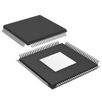
IC DAC 12BIT 800MSPS 100TQFP
Manufacturer
Analog Devices Inc
Series
TxDAC®r
Datasheet
1.AD9785BSVZ.pdf
(64 pages)
Specifications of AD9785BSVZ
Data Interface
Serial
Number Of Bits
12
Number Of Converters
2
Voltage Supply Source
Analog and Digital
Power Dissipation (max)
450mW
Operating Temperature
-40°C ~ 85°C
Mounting Type
Surface Mount
Package / Case
100-TQFP Exposed Pad, 100-eTQFP, 100-HTQFP, 100-VQFP
Resolution (bits)
12bit
Sampling Rate
800MSPS
Input Channel Type
Parallel
Digital Ic Case Style
QFP
No. Of Pins
100
Operating Temperature Range
-40°C To +85°C
Lead Free Status / RoHS Status
Lead free / RoHS Compliant
Settling Time
-
Lead Free Status / RoHS Status
Lead free / RoHS Compliant, Lead free / RoHS Compliant
Available stocks
Company
Part Number
Manufacturer
Quantity
Price
Company:

Part Number:
AD9785BSVZ
Manufacturer:
Analog Devices Inc
Quantity:
135
Company:
Part Number:
AD9785BSVZ
Manufacturer:
Analog Devices Inc
Quantity:
10 000
Company:
Part Number:
AD9785BSVZRL
Manufacturer:
Analog Devices Inc
Quantity:
10 000


Configuring the PLL Band Select Value
The PLL VCO has a valid operating range from approximately
1.0 GHz to 2.0 GHz covered in 63 overlapping frequency bands
as shown in Table 35. For any desired VCO output frequency,
there are multiple valid PLL band select values. Note that the
data shown in Table 35 is for a typical device. Device-to-device
variations can shift the actual VCO output frequency range by
30 MHz to 40 MHz. Also, the VCO output frequency varies as
a function of temperature. Therefore, it is required that the
optimal PLL band select value be determined for each
individual device at the particular operating temperature.
The device has an automatic PLL band select feature on chip.
When enabled, the device determines the optimal PLL band
setting for the device at the given temperature. This setting holds
for a ±60°C temperature swing in ambient temperature. If the
device operates in an environment that experiences a larger
temperature swing, an offset should be applied to the automat-
ically selected PLL band. The following procedure outlines a
method for setting the PLL band select value for a device
operating at a particular temperature that holds for a change in
ambient temperature over the total −40°C to +85°C operating
range of the device without further user intervention. (Note that
REFCLK must be applied to the device during this procedure.)
Configuring PLL Band Select with Temperature Sensing
The values of N1 (Register 0x04, Bits [14:13]) and N2
(Register 0x04, Bits [12:11]) should be programmed along
with the PLL settings shown in Table 34.
1.
2.
3.
Set the PLL Band Select [5:0] value (Register 0x04,
Bits [7:2]) to 63 to enable PLL auto mode.
Wait for the PLL_LOCK pin or the PLL lock indicator
(Register 0x09, Bit 3) to go high. This should occur
within 5 ms.
Read back the 6-bit PLL band select value (Register 0x04,
Bits [7:2]).
Rev. A | Page 49 of 64
4.
Table 36. Setting Optimal PLL Band for Lower Range
(0 to 31) Bands
System Start-Up Temperature
−40°C to −10°C
−10°C to +15°C
15°C to 55°C
55°C to 85°C
Table 37. Setting Optimal PLL Band for Higher Range
(32 to 62) Bands
System Start-Up Temperature
−40°C to −30°C
−30°C to −10°C
−10°C to +15°C
15°C to 55°C
55°C to 85°C
Known Temperature Calibration with Memory
The procedure in the Configuring PLL Band Select with
Temperature Sensing section requires temperature sensing
upon start-up or reset of the device to choose the optimal PLL
band select value to hold over the entire operating temperature
range. If temperature sensing is not available in the system,
another option is to use the automatic PLL band select to
determine the optimal setting for the device when the device is
in a factory environment where the temperature is known. The
optimal band can then be stored in nonvolatile memory.
Whenever the system is powered up or restarted, the optimal
value can be loaded back into the device.
Based on the temperature when the PLL auto mode is
enabled, set the PLL band indicated in Table 36 or Table 37
by rewriting the readback values into the PLL Band Select
[5:0] parameter (Register 0x04, Bits [7:2]).
AD9785/AD9787/AD9788
Set PLL Band to
Readback Band + 3
Readback Band + 2
Readback Band + 1
Readback Band
Readback Band − 1
Set PLL Band to
Readback Band + 2
Readback Band + 1
Readback Band
Readback Band − 1
Related parts for AD9785BSVZ
Image
Part Number
Description
Manufacturer
Datasheet
Request
R

Part Number:
Description:
BOARD EVAL FOR AD9785
Manufacturer:
Analog Devices Inc
Datasheet:

Part Number:
Description:
Dual 16B, 1.0 GSPS TxDAC
Manufacturer:
Analog Devices Inc
Datasheet:

Part Number:
Description:
±1.7g Dual-Axis IMEMS Accelerometer Evaluation Board
Manufacturer:
Analog Devices Inc
Datasheet:
Part Number:
Description:
Inertial Sensor Evaluation System
Manufacturer:
Analog Devices Inc
Datasheet:
Part Number:
Description:
Manufacturer:
Analog Devices Inc
Datasheet:
Part Number:
Description:
Manufacturer:
Analog Devices Inc
Datasheet:
Part Number:
Description:
Manufacturer:
Analog Devices Inc
Datasheet:
Part Number:
Description:
Manufacturer:
Analog Devices Inc
Datasheet:
Part Number:
Description:
Manufacturer:
Analog Devices Inc
Datasheet:
Part Number:
Description:
Manufacturer:
Analog Devices Inc
Datasheet:
Part Number:
Description:
Manufacturer:
Analog Devices Inc
Datasheet:
Part Number:
Description:
Manufacturer:
Analog Devices Inc
Datasheet:
Part Number:
Description:
Manufacturer:
Analog Devices Inc
Datasheet: