06123C104KAT2A AVX Corporation, 06123C104KAT2A Datasheet - Page 3
06123C104KAT2A
Manufacturer Part Number
06123C104KAT2A
Description
CAPACITOR CERAMIC, 0.1UF, 25V, X7R, 0612
Manufacturer
AVX Corporation
Series
0612r
Datasheet
1.0612ZC225MAT2A.pdf
(4 pages)
Specifications of 06123C104KAT2A
Dielectric Characteristic
X7R
Capacitance
0.1µF
Capacitance Tolerance
± 10%
Voltage Rating
25VDC
Capacitor Case Style
0612
No. Of Pins
2
Capacitor Mounting
SMD
Rohs Compliant
Yes
Tolerance
10 %
Operating Temperature Range
- 55 C to + 125 C
Temperature Coefficient / Code
X7R
Package / Case
0612 (1632 metric)
Product
Low Inductance MLCCs
Dimensions
0.063 in W x 0.126 in L x 0.560 mm H
Dissipation Factor Df
3
Termination Style
SMD/SMT
Lead Free Status / Rohs Status
Details


Low Inductance Capacitors (RoHS)
0612/0508/0306/0204 LICC (Low Inductance Chip Capacitors)
GENERAL DESCRIPTION
The key physical characteristic determining equivalent
series inductance (ESL) of a capacitor is the size of the
current loop it creates. The smaller the current loop, the
lower the ESL.
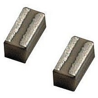
A standard surface mount MLCC is rectangular in shape
with electrical terminations on its shorter sides. A Low
Inductance Chip Capacitor (LICC) sometimes referred to
as Reverse Geometry Capacitor (RGC) has its
terminations on the longer sides of its rectangular shape.
The image on the right shows the termination differences
between an MLCC and an LICC.
When the distance between terminations is reduced, the
size of the current loop is reduced. Since the size of the
current loop is the primary driver of inductance, an 0306
with a smaller current loop has significantly lower ESL
then an 0603. The reduction in ESL varies by EIA size,
however, ESL is typically reduced 60% or more with an
LICC versus a standard MLCC.
AVX LICC products are available with a lead-free finish of
plated Nickel/Tin.
HOW TO ORDER
NOTE: Contact factory for availability of Termination and Tolerance Options for Specific Part Numbers.
TYPICAL IMPEDANCE CHARACTERISTICS
0.001
0612
0.01
0204
0306
0508
0612
Size
0.1
10
1
1
6 = 6.3V
Voltage
Y = 16V
Z = 10V
3 = 25V
5 = 50V
4 = 4V
Z
10
Frequency (MHz)
Dielectric
W = X6S
C = X7R
D = X5R
Z = X7S
D
100
MLCC_0805
LICC_0508
Number of Zeros
Capacitance
2 Sig. Digits +
Code (In pF)
105
1000
Capacitance
Tolerance
M = ±20%
K = ±10%
M
PERFORMANCE CHARACTERISTICS
Capacitance Tolerances
Operation
Temperature Range
Temperature Coefficient
Voltage Ratings
Dissipation Factor
Insulation Resistance
(@+25°C, RVDC)
0.001
0.01
0.1
10
1
Failure Rate
1
A = N/A
A
MLCC
Terminations
T = Plated Ni
and Sn
10
K = ±10%; M = ±20%
X7R = -55°C to +125°C
X5R = -55°C to +85°C
X7S = -55°C to +125°C
X7R, X5R = ±15%; X7S = ±22%
4, 6.3, 10, 16, 25 VDC
4V, 6.3V = 6.5% max; 10V = 5.0% max;
100,000MΩ min, or 1,000MΩ per
Frequency (MHz)
T
μF min.,whichever is less
16V = 3.5% max; 25V = 3.0% max
4 = 13" Reel
Packaging
2 = 7" Reel
Available
MLCC_1206
LICC
2
100
LICC_0612
0.35 (0.014)
0.56 (0.022)
0.61 (0.024)
0.76 (0.030)
1.02 (0.040)
1.27 (0.050)
Thickness
Thickness
mm (in)
A*
1000
61
Related parts for 06123C104KAT2A
Image
Part Number
Description
Manufacturer
Datasheet
Request
R

Part Number:
Description:
Manufacturer:
AVX Corporation
Datasheet:
Part Number:
Description:
Manufacturer:
AVX Corporation
Datasheet:
Part Number:
Description:
Manufacturer:
AVX Corporation
Datasheet:
Part Number:
Description:
Manufacturer:
AVX Corporation
Datasheet:
Part Number:
Description:
Manufacturer:
AVX Corporation
Datasheet: