87106-205 AVX Corporation, 87106-205 Datasheet - Page 19
87106-205
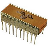
Manufacturer Part Number
87106-205
Description
CAPACITOR CERAMIC, 4.7UF, 500V, X7R, DIP
Manufacturer
AVX Corporation
Datasheet
1.SM049C225KBN290.pdf
(21 pages)
Specifications of 87106-205
Dielectric Characteristic
X7R
Capacitance
4.7µF
Capacitance Tolerance
± 10%
Voltage Rating
500VDC
Capacitor Case Style
DIP
No. Of Pins
20
Capacitor Mounting
Through Hole
Rohs Compliant
No


SMPS Stacked MLC Capacitors
(SM9 Style) Technical Information on SMPS Capacitors
ELECTRICAL SPECIFICATIONS
Temperature Coefficient
C0G: A Temperature Coefficient - 0 ±30 ppm/°C, -55° to +125°C
X7R: C Temperature Coefficient - ±15%, -55° to +125°C
Z5U: E Temperature Coefficient - +22, -56%, +10° to +85°C
Capacitance Test (MIL-STD-202 Method 305)
C0G: 25°C, 1.0±0.2 Vrms (open circuit voltage) at 1KHz
X7R: 25°C, 1.0±0.2 Vrms (open circuit voltage) at 1KHz
Z5U: 25°C, 0.5 Vrms max (open circuit voltage) at 1KHz
Dissipation Factor 25°C
C0G: 0.15% Max @ 25°C, 1.0±0.2 Vrms (open circuit voltage) at 1KHz
X7R: 2.5% Max @ 25°C, 1.0±0.2 Vrms (open circuit voltage) at 1KHz
Z5U: 3.0% Max @ 25°C, 0.5 Vrms max (open circuit voltage) at 1KHz
Insulation Resistance 25°C (MIL-STD-202 Method 302)
C0G and X7R: 100K MΩ or 1000 MΩ-μF, whichever is less.
Z5U: 10K MΩ or 1000 MΩ-μF, whichever is less.
Insulation Resistance 125°C (MIL-STD-202 Method 302)
C0G and X7R: 10K MΩ or 100 MΩ-μF, whichever is less.
Z5U: 1K MΩ or 100 MΩ-μF, whichever is less.
HOW TO ORDER
Note: Capacitors with X7R and Z5U dielectrics are not intended for applications
26
Size
SM9 = Plastic
AVX Style
across AC supply mains or AC line filtering with polarity reversal. Contact plant
for recommendations.
SM9
Case
dimen-
chart
See
sions
Size
1
500V = 7
Voltage
100V = 1
200V = 2
50V = 5
7
Temperature
Coefficient
C0G = A
X7R = C
Z5U = E
C
ESR @ 10KHz
ESR @ 50KHz
ESR @ 100KHz
ESR @ 500KHz
ESR @ 1MHz
ESR @ 5MHz
ESR @ 10MHz
220,000 pF = 224
22,000 pF = 223
1,000 pF = 102
100 pF = 101
100 μF = 107
Capacitance
10 pF = 100
(2 significant C0G: J = ±5%
10 μF = 106
AVX Styles: SM91, SM92, SM93, SM94, SM95, SM96
digits + no.
1 μF = 105
of zeros)
106
Code
Typical ESR Performance (mΩ)
Electrolytic
100μF/50V
Aluminum
300
285
280
265
265
335
560
Dielectric Withstanding Voltage 25°C (Flash Test)
C0G and X7R: 250% rated voltage for 5 seconds with 50 mA max
Z5U: 200% rated voltage for 5 seconds with 50 mA max charging
Life Test (1000 hrs)
C0G and X7R: 200% rated voltage at +125°C. (500 Volt units @
Z5U: 150% rated voltage at +85°C
Moisture Resistance (MIL-STD-202 Method 106)
C0G, X7R, Z5U: Ten cycles with no voltage applied.
Thermal Shock (MIL-STD-202 Method 107, Condition A)
Immersion Cycling (MIL-STD-202 Method 104, Condition B)
Resistance To Solder Heat (MIL-STD-202, Method 210,
*
X7R: K = ±10%
Z5U: Z = +80, -20%
Hi-Rel screening for C0G and X7R only. Screening consists of 100% Group A
(B Level), Subgroup 1 per MIL-PRF-49470.
Capacitance
charging current. (500 Volt units @ 750 VDC)
600 VDC)
Condition B, for 20 seconds)
current.
Tolerance
M = ±20%
M = ±20%
K = ±10%
P = GMV (+100, -0%)
Z = +80, -20%
M
Solid Tantalum
100μF/10V
Low ESR
72
67
62
56
56
72
91
B = Hi-Rel
A = Standard
Level
Test
A
Solid Aluminum
Electrolytic
100μF/16V
*
29
22
20
18
17
17
22
Termination
N = Straight Lead
J = Leads formed
L = Leads formed
in
out
N
100μF/50V
MLCC
SMPS
12.5
2.5
20
3
2
4
7
page 28 for
4.7μF/50V
See table
Height
max cap.
MLCC
660
SMPS
height
7.5
per
66
23
15
14
on
8
8
Related parts for 87106-205
Image
Part Number
Description
Manufacturer
Datasheet
Request
R

Part Number:
Description:
CAP CER 68UF 200V X7R 40-DIP
Manufacturer:
AVX Corporation
Datasheet:
Part Number:
Description:
TEST PER D.E.S.C. 87106. *LEADS TO BE STRAIGHT 100% THERMAL SHOCK & BURN-IN 100 HR 600 VOLTS, @+125C. 100% CAP, DF, RTIR, HTIR, & DWV.
Manufacturer:
AVX Corporation

Part Number:
Description:
Manufacturer:
AVX Corporation
Datasheet:
Part Number:
Description:
CAPACITOR CERAMIC, 1.2UF, 100V, X7R, DIP
Manufacturer:
AVX Corporation
Datasheet:
Part Number:
Description:
Manufacturer:
AVX Corporation
Datasheet:
Part Number:
Description:
Manufacturer:
AVX Corporation
Datasheet:

Part Number:
Description:
CAPACITOR CERAMIC, 3.3UF, 50V, X7R, DIP
Manufacturer:
AVX Corporation
Datasheet:

Part Number:
Description:
CAPACITOR CERAMIC, 47UF, 50V, X7R, DIP
Manufacturer:
AVX Corporation
Datasheet:

Part Number:
Description:
CAPACITOR CERAMIC, 2.2UF, 200V, X7R, DIP
Manufacturer:
AVX Corporation
Datasheet: