C052C104K5R5TA Kemet, C052C104K5R5TA Datasheet - Page 7
C052C104K5R5TA
Manufacturer Part Number
C052C104K5R5TA
Description
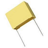
CAPACITOR CERAMIC, 0.1UF, 50V, X7R, Radial
Manufacturer
Kemet
Type
Radialr
Datasheet
1.C052C102J1G5CA.pdf
(16 pages)
Specifications of C052C104K5R5TA
Dielectric Characteristic
X7R
Capacitance
0.1µF
Capacitance Tolerance
± 10%
Voltage Rating
50VDC
Capacitor Case Style
Radial Leaded
No. Of Pins
2
Capacitor Mounting
Through Hole
Rohs Compliant
Yes
Package/case
4.83 X 2.29 X 4.83
Mounting
Through Hole
Capacitance Value
0.1 uF
Dielectric
X7R
Tolerance
10 %
Voltage
50 Vdc
Lead Pitch For Radial
5.08 mm
Product Length
4.83 mm
Product Depth
2.29 mm


GENERAL SPECIFICATIONS
ELECTRICAL
Working Voltage:
C0G – 50, 100, 200
X7R – 50, 100, 200
Temperature Characteristics:
C0G 0 ±30 PPM / °C from -55°C to +125°C
X7R ± 15% from -55°C to +125°C
Capacitance Tolerance:
C0G ±0.5pF, ±1%, ±2%, ±5%, ±10%, ±20%
X7R ±10%, ±20%, -0 +100%, +80% / -20%
Construction:
Monolithic block of ceramic dielectric with
Interdigitated internal electrodes, encapsulated
in a molded case, and having axial or radial leads.
Meets flame test requirements of UL Standard 94V-0.
Lead Material:
Axial: Solder coated copper clad steel
Radial: Solder-coated copper standard (100% tin
plated optional)
Solderability:
MIL-STD-202, Method 208, Sn62 solder, 245°C for
5 ±1/2 seconds.
Terminal Strength:
Capacitance:
Within specified tolerance and when measured with
1 volt rms at 1kHz (1000 pF or less at 1 MHz for C0G).
Dissipation Factor @25°C:
25°C at 1kHz (1000 pF or less at 1 MHz for C0G).
C0G – 0.15% maximum
X7R – 2.5% maximum
Insulation Resistance:
After 2 minutes electrification at 25°C and rated voltage
C0G – 100K M or 1000 M – F, whichever is less.
X7R – 100K M
Dielectric Withstanding Voltage:
250% of rated voltage for 5 seconds with current limited
to 50 mA at 25°C.
EIA-198 Method 303, Condition A (2.2 kg)
(±0.5pF is tightest tolerance available)
© KEMET Electronics Corporation, P.O. Box 5928, Greenville, S.C. 29606, (864) 963-6300
or 1000 M
CERAMIC MOLDED AXIAL & RADIAL
– F, whichever is less.
PERFORMANCE CHARACTERISTICS
ELECTRICAL
5 ±1/2 seconds.
Terminal Strength:
Capacitance:
Within specified tolerance and when measured with
1 volt rms at 1kHz (1000 pF or less at 1 MHz for C0G).
Dissipation Factor @25°C:
25°C at 1kHz (1000 pF or less at 1 MHz for C0G).
C0G – 0.15% maximum
X7R – 2.5% maximum
Insulation Resistance:
After 2 minutes electrification at 25°C and rated voltage
C0G – 100K M or 1000 M – F, whichever is less.
X7R – 100K M
Dielectric Withstanding Voltage:
250% of rated voltage for 5 seconds with current limited
to 50 mA at 25°C.
EIA-198 Method 303, Condition A (2.2 kg)
or 1000 M
– F, whichever is less.
27
Related parts for C052C104K5R5TA
Image
Part Number
Description
Manufacturer
Datasheet
Request
R

Part Number:
Description:
CAP, KEMET #F601BL105K250C
Manufacturer:
Kemet
Datasheet:
Part Number:
Description:
Manufacturer:
Kemet
Datasheet:
Part Number:
Description:
Manufacturer:
Kemet
Datasheet: