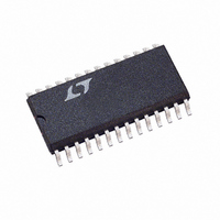
LTC1458ISW Linear Technology, LTC1458ISW Datasheet - Page 9

LTC1458ISW
Manufacturer Part Number
LTC1458ISW
Description
IC D/A CONV 12BIT R-R QUAD28SOIC
Manufacturer
Linear Technology
Datasheet
1.LTC1458CSWPBF.pdf
(12 pages)
Specifications of LTC1458ISW
Settling Time
14µs
Number Of Bits
12
Data Interface
Serial
Number Of Converters
4
Voltage Supply Source
Single Supply
Power Dissipation (max)
5.5mW
Operating Temperature
-40°C ~ 85°C
Mounting Type
Surface Mount
Package / Case
28-SOIC (7.5mm Width)
Lead Free Status / RoHS Status
Contains lead / RoHS non-compliant
Available stocks
Company
Part Number
Manufacturer
Quantity
Price
Part Number:
LTC1458ISW
Manufacturer:
LINEAR/凌特
Quantity:
20 000
APPLICATIO S I FOR ATIO
Using Two DACs to Digitally Program the Full Scale
and Offset of a Third
Figure 2 shows how to use one LTC1458 to make a 12-bit
DAC with a digitally programmable full scale and offset.
DAC A and DAC B are used to control the offset and full
scale of DAC C. DAC A is connected in a 1 configuration
and controls the offset of DAC C by moving REFLO C above
ground. The minimum value to which this offset can be
programmed is 10mV. DAC B is connected in a
configuration and controls the full scale of DAC C by
driving REFHI C. Note that the voltage at REFHI C must be
less than or equal to V
U
CC
/2, corresponding to DAC B’s code
U
V
OUT
500
W
U
X1/X2 C
V
CS/LD
D
REFHI C
GND
REFLO C
REFLO D
REFHI D
D
CLK
NC
V
X1/X2 D
OUT C
IN
OUT
OUT D
Figure 2
2
LTC1458L
LTC1458
mode for full rail-to-rail output swing.
The transfer characteristic is:
where REFOUT = The Reference Output
D
D
D
A
B
C
2,500 for V
V
= (DAC A Digital Code)/4096
= (DAC B Digital Code)/4096
= (DAC C Digital Code)/4096
REFLO B
REFLO A
REFHI B
REFHI A
REFOUT
OUTC
X1/X2 B
X1/X2 A
V
V
This sets the offset.
This sets the full scale.
OUT B
OUT A
GND
CLR
V
V
NC
CC
CC
= 2 • [D
CC
= 5V, since DAC C is being operated in 2
C
• (2 • D
1458 F02
LTC1458/LTC1458L
B
– D
A
) + D
0.1 F
A
] • REFOUT
5V
9


